


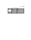


Stack Operations
2-3
2
Remote Connections
Prior to accessing the switch’s onboard agent via a network connection, you must
first configure it with a valid IP address, subnet mask, and default gateway using a
console connection, DHCP or BOOTP protocol.
The IP address for this switch is obtained via DHCP by default. To manually
configure this address or enable dynamic address assignment via DHCP or BOOTP,
see “Setting an IP Address” on page 2-5.
Note: This switch supports four concurrent Telnet/SSH sessions.
After configuring the switch’s IP parameters, you can access the onboard
configuration program from anywhere within the attached network. The onboard
configuration program can be accessed using Telnet from any computer attached to
the network. The switch can also be managed by any computer using a web
browser (Internet Explorer 5.0 or above, or Netscape Navigator 6.2 or above), or
from a network computer using SNMP network management software.
Note: The onboard program only provides access to basic configuration functions. To
access the full range of SNMP management functions, you must use
SNMP-based network management software.
Stack Operations
Up to eight switches can be stacked together as described in the Installation Guide.
One unit in the stack acts as the Master for configuration tasks and firmware
upgrade. All of the other units function in Slave mode.
To configure any unit in the stack, first verify the unit number by counting down from
the Master unit, and then select the appropriate unit number from the web or
console management interface.
Selecting the Stack Master
Note the following points about unit numbering:
• When the stack is initially powered on, the Master unit is designated as unit 1. The
stack is simply numbered from top to bottom, with the first unit in the stack
designated at unit 1. This unit identification number can be selected on the front
panel graphic of the web interface, or from the CLI.
• If more than one stack Master is selected using the Master push button on the
switch’s front panel, the stack will not function.
• If any unit fails, the stack will not function. You must replace the failed unit, and
reconnect the stacking cables to restore a ring topology.
• If a unit in the stack fails or is removed from the stack, the unit numbers will not
change. This means that when you replace a unit in the stack, the original
configuration for the failed unit will be restored to the replacement unit.