


Operation
26
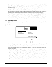
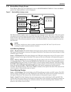
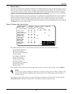
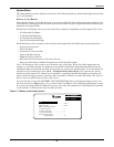
3.2.3 Walk-In Display Screen
From the Master Menu, highlight WALK-IN DISPLAY and then press the Select pad.
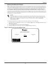
The Walk-In Display screen enables the operator to monitor the UPS module DC bus voltage, the
input currents and the output voltage. This is important during the start-up procedures.
During start-up, the UPS input circuit breaker is closed and power is applied to the UPS module. The
Walk-In Display screen graphically shows the voltage increasing on the DC bus as the UPS module
rectifier begins to walk-in.
The DC Volts bar gradually moves to the right. After the DC Volts bar reaches the 90% level, the UPS
module inverter starts-up and the Output Volts bar also moves to the right. Both the DC Volts and
the Output Volts bars should settle near the 100% line as the UPS module becomes fully energized.
The three Input Amps bars (one for each phase of input current) move to the right during the initial
transformer inrush. They should return to the left after the momentary inrush has subsided, then
increase to about 10% as the DC Volts increase.
Modules equipped with the optional input filter will indicate more than 10% with no connected load.
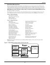
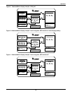
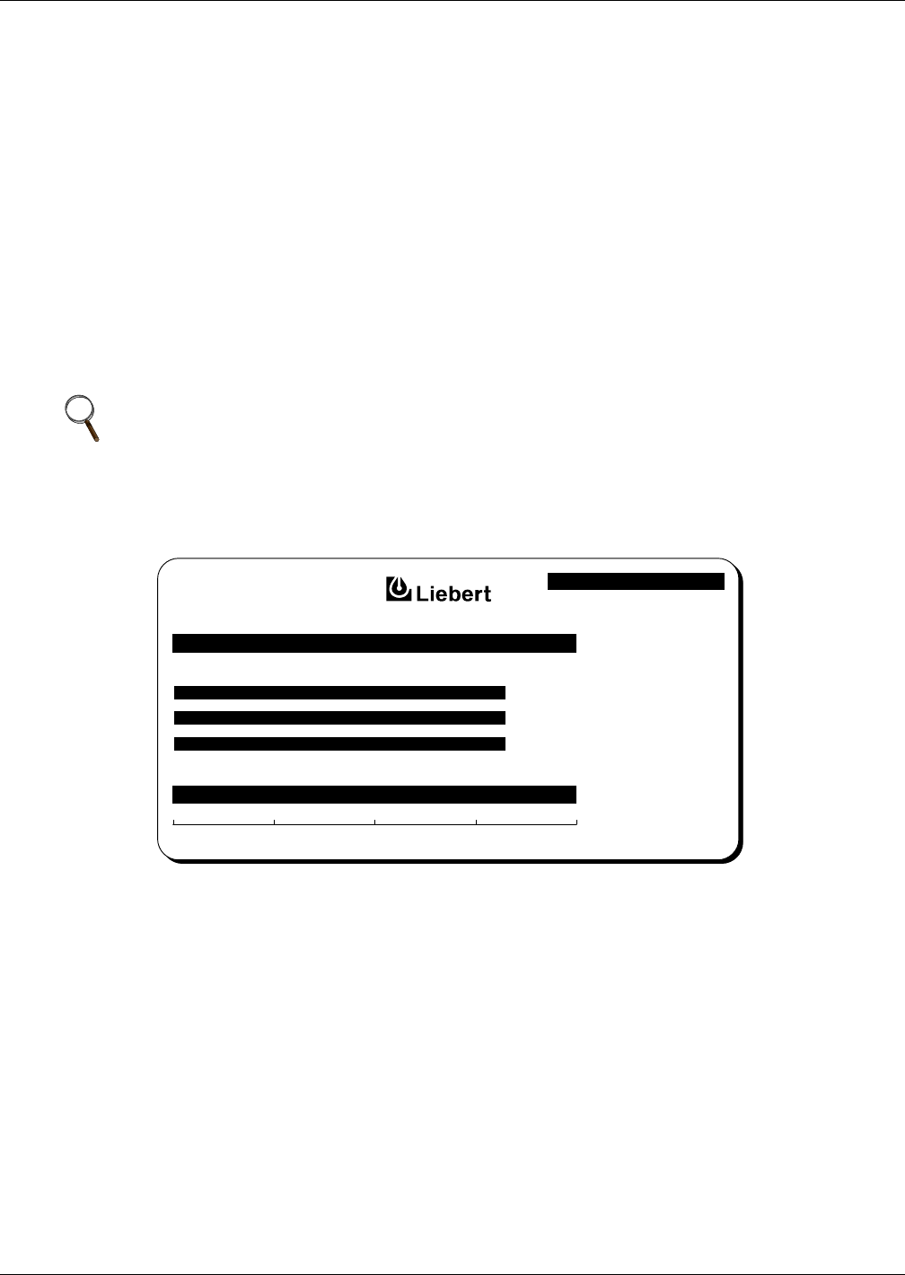
Figure 12 Walk-in display screen
NOTE
After the critical load is transferred from the bypass line to the UPS modules, the Input Amps
bars continue to indicate the percent of the design input current to the UPS rectifier.
If any Input Amps bar differs from the average bar length by more than 10%, call Liebert
Global Services.
DOWN :
SELECT :
MASTER MENU
SELECT :
0% 25% 50% 75% 100%
INPUT AMPS
OUTPUT VOLTS
D.C. VOLTS
© 1989-2003