


Operation
72
STEP 4 (Start-Up Procedure)
a. Press the Select pad to put the Master Menu on the LCD. Move the highlighted cursor to
Start-Up Procedures (use the Up and Down pads). Press the Select pad to display the Start-
Up Procedures screen (Figure 52). Return to this screen whenever you need to see the start-
up instructions.
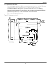
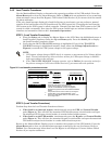
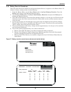
b. Select the Monitor/Mimic Display on the LCD. In the ALARM MESSAGES block (Figure 7),
the only alarms present should be Battery CB Open and Load On Bypass. If any other alarm
messages are present, do not proceed with the UPS start-up. Contact Liebert Global Services
(LGS) for assistance.
c. Select the Walk-In screen on the LCD.
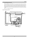
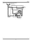
d. To energize the UPS module, manually close the input circuit breaker (CB1, Figure 3). This will
provide power to the rectifier. Use the Walk-In screen to monitor the Module DC Bus voltage.
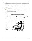
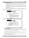
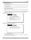
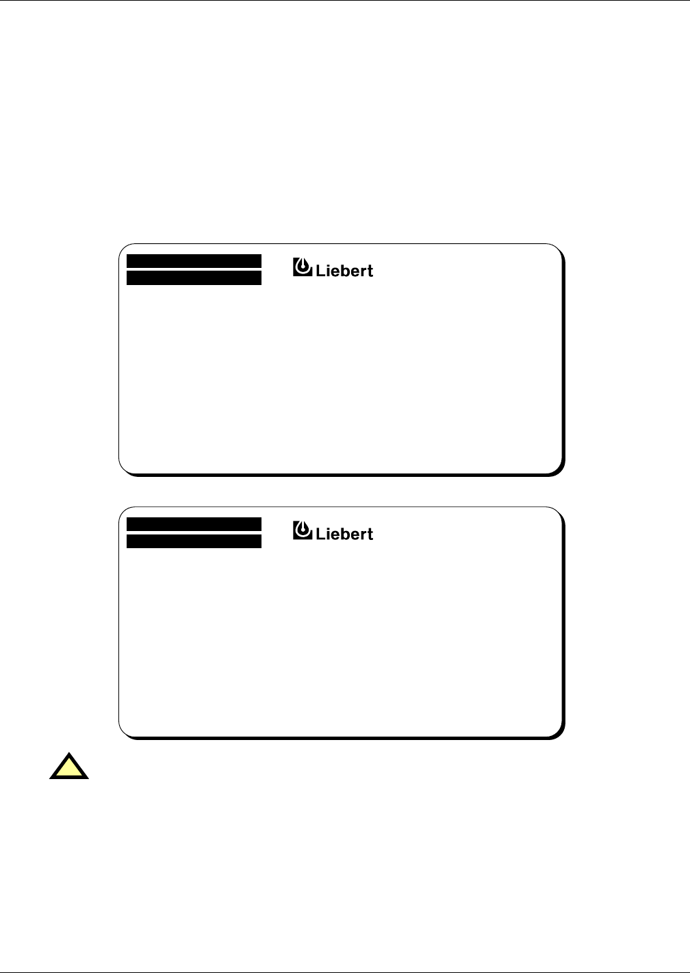
Figure 52 Start-up procedures screen
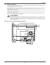
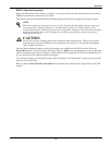
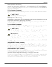
Figure 53 Start-up procedures, continued
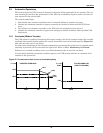
The Input Amps bars should settle at 25% or less after the momentary inrush current has subsided.
Verify that the DC Voltage bar begins to gradually move to the right.
Verify that the Output Voltage bar moves to the right after the DC Voltage bar has reached the 90%
level. Both bars should settle near the 100% line.
Select the Monitor/Mimic display from the Master Menu and confirm that the module DC bus and AC
output are at their proper operating voltages.
!
WARNING
If any abnormal situation occurs during this walk-in procedure, open the input circuit breaker
and investigate the problem. Each input amps bar should be within 25% of the average bar
length. Call Liebert Global Services if you need help.
START-UP PROCEDURES
1. Wait approximately two (2) minutes before attempting any other action .
2. Select "SYSTEM CONFIGURATION" screen to verify that the correct model number is
displayed.
3. Select "WALK-IN" screen and do the following:
a) Close module input circuit breaker. Verify that the DC voltage bar on
the display begins to gradually move to the right and the AC input current
bars do not move to the right more than 10% (40% for modules
with input filters) after the transformer inrush has subsided.
b) Verify that the output voltage bar moves to the right after the DC
bus bar has reached the 90% point. Both bars should settle near
their respective 100% levels.
NEXT PAGE
MASTER MENU
DOWN :
SELECT :
START-UP PROCEDURES (Cont'd)
c) If anything happens on the display not mentioned in (a) or (b),
immediately open the module input circuit breaker and investigate.
4. If step 3 is successful, select "MONITOR/MIMIC" screen and verify module
DC bus and output voltages are at proper nominal level. If so, close
module battery circuit breaker.
5. If bypass or static switch circuit breakers (contactor on xxxxx-xx)
are open, refer to Start-Up Procedures in the UPS Manual for instructions
on closing these breakers.
6. System is now ready to assume load. Select "LOAD TRANSFER PROCEDURES"
screen for this procedure.
FIRST PAGE
MASTER MENU
UP :
SELECT :