


Operation
38
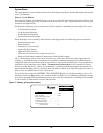
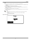
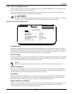
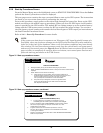
Figure 26 Battery test screen
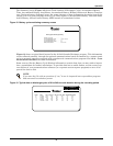
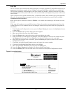
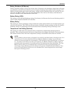
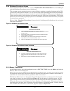
Figure 27 Battery test results screen
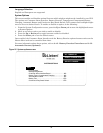
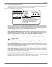
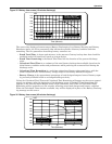
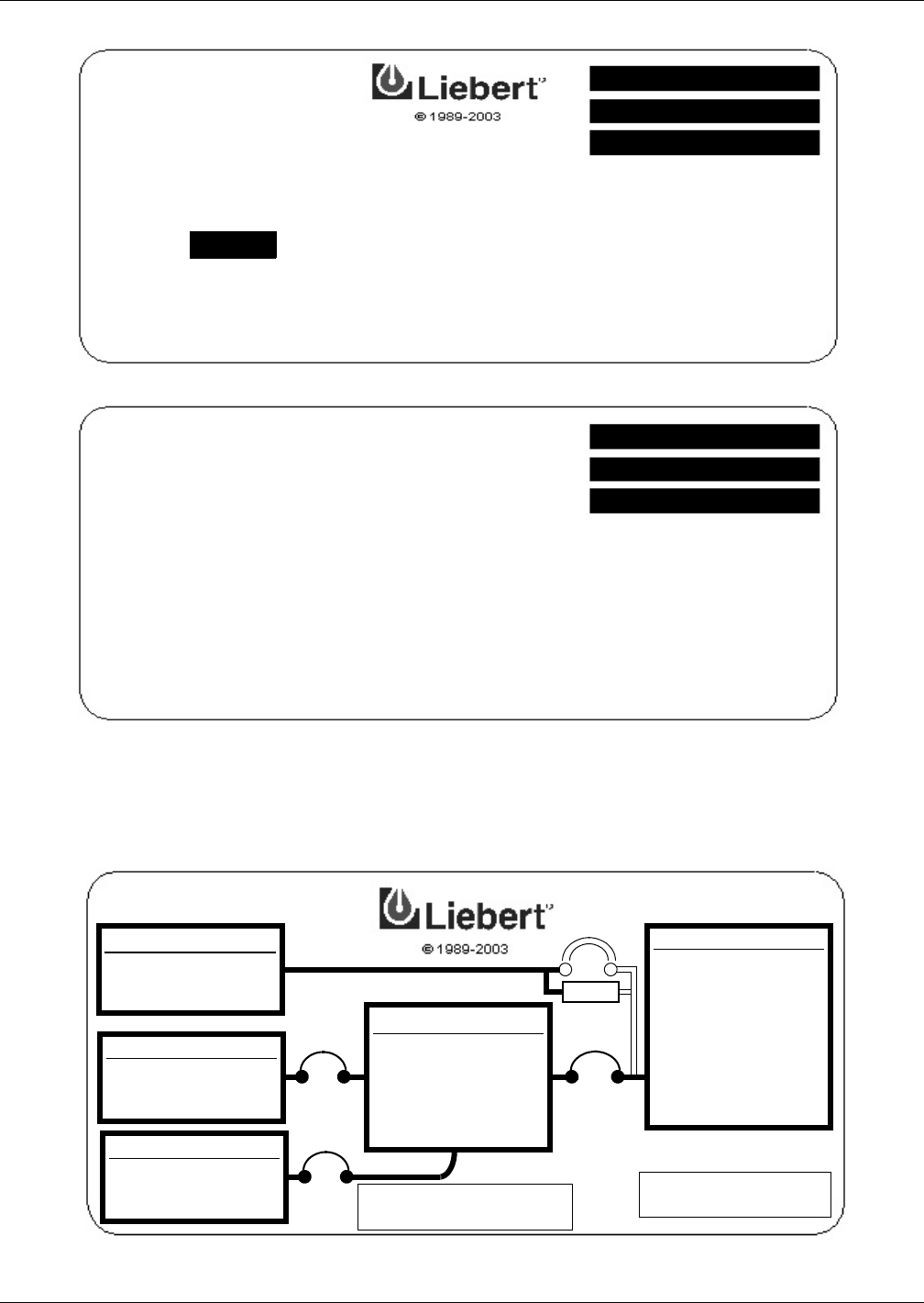
Continuous Duty Static Switch (Optional)
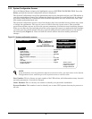
This feature requires installation of a Customer Alarm Interface board. When the CDSS feature is
enabled and the Customer Alarm Interface option is installed and enabled, the mimic display will be
modified to include a box in parallel with the bypass circuit breaker. The box will be labeled CDSS.
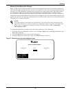
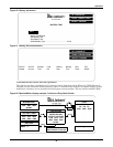
Figure 28 Monitor/Mimic display example: Continuous Duty Static Switch
Battery Test Results
Start Battery Test
Stop Battery Test
Select Battery Type...............................................15 min
EXIT
BATTERY TEST
UP: CURSOR UP
DOWN: CURSOR DOWN
SELECT: CHOOSE
End DC
Voltage
End DC
Current
Elapsed
Time
Load
kW
Starting
Date
Test
Result
Start
Temp.
Starting
Time
UP: CURSOR UP
DOWN: CURSOR DOWN
SELECT: CHOOSE
BYPASS INPUT
∅A-B ∅B-C ∅C-A
479V 480V 480V
60.0Hz
UPS INPUT PWR
∅A-B ∅B-C ∅C-A
480V 480V 480V
390A 390A 390A
UPS RATINGS
AP658-64
RATED 500 KVA
OUTPUT VOLTAGE
∅A-B ∅B-C ∅C-A
480V 480V 480V
60.0Hz
LOAD
270 KVA
∅A ∅B ∅C
325A 325A 325A
OK to Transfer
Static Switch Connected
BATTERY
VOLTS 540
AMPS 0
Load On Bypass
CDSS