Operation
71
STEP 3 (Start-Up Procedure)
During a start-up procedure, power is supplied to the critical load through the internal bypass line
while the UPS module is being energized. Depending on the reason for your UPS module shutdown,
you may already have power through the bypass line. You can determine this by observing the Moni-
tor/Mimic Display screen now that Control Power is available. If the bypass line is not supplying the
load, energize the bypass line by doing the following:
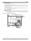
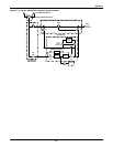
a. Close the Bypass Input Breaker (BIB), external to the UPS. This breaker may be in your
Maintenance Bypass Cabinet.
b. Observe the Monitor/Mimic Display screen to determine if your UPS Bypass circuit breaker is
closed and whether the UPS Bypass line is supplying power to the critical load. If your Bypass
circuit breaker is open (as in recovering from an Emergency Power Off or Low Battery
Shutdown), close this circuit breaker as follows:
1. Open the UPS control panel door and find the Transfer Relay Board (on the top cross
member of the frame). If the red LED (CR18) labeled TOT S/D (Total Shutdown) is on,
press the Bypass Reset switch (SW1) on this board. The red LED should turn off.
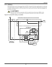
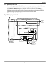
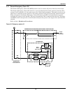
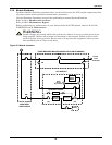
2. Set the Static Switch Disconnect (Figure 50 or Figure 51) to OFF (open).
3. Find the Close B.P. switch (see Figure 3, Item 5) on the main logic board. Press this
switch to close the UPS Bypass circuit breaker. Check the Monitor/Mimic screen to verify
the breaker is closed.
4. Set the Static Switch Disconnect to ON (closed) by closing the fuseholder.
5. Close the UPS module doors.
c. If the UPS Bypass line is available, but not yet supplying power to the load, close the circuit
breakers (external to the UPS) required to provide power to the critical load equipment. If you
have a Maintenance Bypass, this will include the Maintenance Isolation Breaker (MIB).
1. Verify the Bypass Input Breaker (BIB) and UPS Bypass circuit breakers are closed.
2. Close the Maintenance Isolation Breaker (MIB).
3. Open the Maintenance Bypass Breaker (MBB).
Observe the Monitor/Mimic Display screen to confirm that the UPS Bypass line is energized and sup-
plying power to the critical load equipment.
!
CAUTION
DO NOT assume that the UPS Bypass Breaker is closed.
Instructions for operating the Maintenance Bypass circuit breakers are on the Maintenance
Bypass cabinet. Make sure you understand the proper sequence before operating any circuit
breaker. Operating a Maintenance Bypass circuit breaker out of sequence could cut off power
to the critical load.
NOTE
The static switch disconnects are controlled by a pair of fuseholders labeled Static Disconnect
and mounted on the frame adjacent to the Static Switch. Refer to the drawing of your UPS
system. They typically are labeled F21 and F22.
!
CAUTION
Make sure you understand the proper sequence before operating any circuit breaker.
Operating a Maintenance Bypass circuit breaker out of sequence could cut off power to the
critical load. Operations involving MIB and MBB must be done ONLY when the UPS system
is on internal bypass.


