


14 Theory of Operation
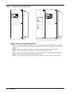
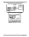
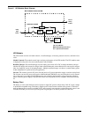
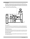
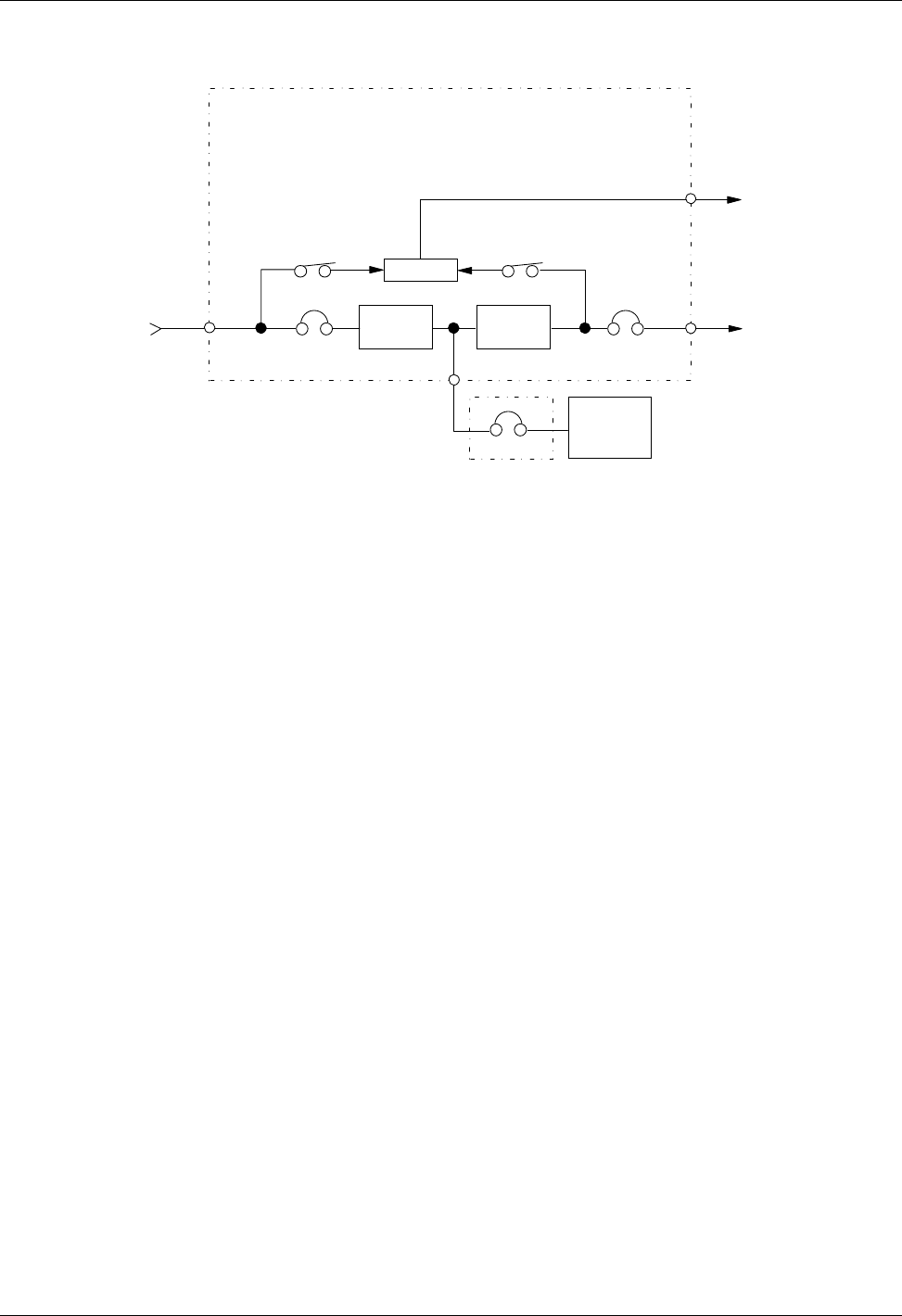
Figure 6 UPS Module Block Diagram
UPS Module
The UPS module consists of module controls, a rectifier/charger, an inverter, protective devices, and other acces-
sories.
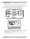
Module Controls: The module control logic monitors performance of the UPS module. The UPS module status
is displayed locally and is also sent to the System Control Cabinet.
Rectifier/Charger: The rectifier/charger converts utility power from AC to DC to charge the battery and pro-
vide the DC input to the inverter. Its design limits reflected harmonic current distortion to source power and pro-
vides low-ripple DC power for charging batteries. Multiple rectifier/chargers can share a common battery plant,
if that configuration is preferred for your application.
Inverter: The inverter converts DC power into the precise AC power required to supply a sensitive critical load.
The inverter converts DC power into a pulse-width-modulated (PWM)/six-step waveform that is easily filtered
into a clean sine wave output. The PWM/stepwave also minimizes the harmonic voltage distortion caused by
typical switching power supplies and other non-linear load components used in computers and related electron-
ics.
Battery Plant
The battery is used as the alternate source of power to supply DC power to the inverter if the AC supply voltage
is outside the acceptable range. The battery supplies power to the inverter until the utility power is restored or
untilan alternate power source is available. If AC source power is not restored or an alternate power source is not
available, the battery can be sized to provide power long enough for an orderly shutdown of the load.
CB- CircuitBreaker
MBD - Module Battery Disconnect
SCC- SystemControl Cabinet
Rectifier/
Charger
Controls
CONTROL POWER
MULTI-MODULE UPS SYSTEM
Inverter
MBD
Utility
Input
Power
Control
Wiring
To SCC
Battery
Output
Power
To SCC
Output
CB
Input
CB