


Operation 57
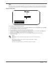
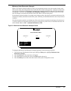
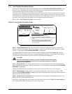
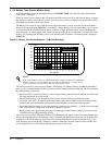
3.1.7 Load Transfer Procedures Screen
Go to the SCC Master Menu and move the highlighted cursor to LOAD TRANSFER PROCEDURES. Note
that this screen is displayed at the System Control Cabinet but is not required at the UPS modules. Press the
Select pad and the Load Transfer Procedures screen is displayed.
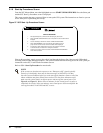
The Load Transfer Procedures screen contains instructions to transfer the critical load between the UPS system
and the bypass line. Comparisons of the UPS and bypass voltage, frequency, and phase synchronization are dis-
played along with transfer status messages and an indication of circuit breaker overlap time. The metered param-
eter values on the Load Transfer Procedures screen are updated at half-second intervals.
Refer to 3.3.2 - Load Transfer Procedures for more details.
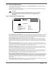
Figure 36 Load Transfer Procedures Screen
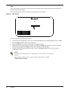
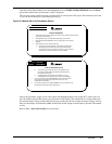
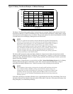
Item 1 - Voltage Comparisons. This chart shows the UPS and bypass voltage and frequency comparisons
between each of the three phases. If the UPS and bypass voltages are not within specified tolerances, a manual
transfer is not permitted and TRANSFER PROHIBIT is highlighted.
The Voltage Adjust knob (push-to-turn), located on the SCC Operator Control Panel (Figure 10), is used to
match the UPS output voltage to the bypass voltage. When the UPS and bypass voltages match within the spe-
cific tolerance, a manual transfer is possible and OK TO TRANSFER is highlighted.
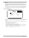
Item 2 - Synchronization. This display shows the phase synchronization between the UPS output and bypass
power. If the phase displacement is outside of the tolerance, a manual transfer is not permitted and TRANSFER
PROHIBIT is highlighted.
During normal operation, the synchronization display should read UPS LEAD from zero to 4 degrees.
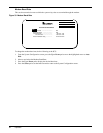
Item 3 - Status Messages. Three messages are constantly displayed here. Only the active message is high-
lighted. If TRANSFER PROHIBIT is highlighted, manual transfers/retransfers cannot be performed, and auto-
matic retransfers will not be initiated.
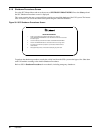
Item 4 - Manual Transfer Instructions. These instructions assist the operator in transferring the critical load
between the UPS system and the bypass line.
If the load is on the bypass line, step 2 on the screen will instruct you to press the UPS and Control Enable but-
tons to retransfer the load from the bypass line to the UPS system.
CAUTION
The UPS output voltage responds very slowly to inputs from the Voltage Adjust
knob. Make small adjustments and wait several seconds each time for voltage to
stabilize before continuing.
OUTPUT VOLTS
OUTPUTAMPS
OUTPUT FREQUENCY
LOAD KVA
BYPASS VOLTS
A
380
530
380
DC
B
380
530
380
TIMELOAD
349
C
380
530
380
HERTZ
50.0
NEXT FRAME
PREVIOUS FRAME
EXIT
UP :
DOWN :
SELECT :
HISTORY STATUS MODULE-0 04/10/97 16:49:21 FRAME 36
ORDER - 000000 SITE ID - 00000 SITE TAG - 0000000
**** ACTIVE ALARMS**** Output Ov-volts
OUTPUT VOLTS
OUTPUTAMPS
OUTPUT FREQUENCY
OUTPUT VOLTS
OUTPUTAMPS
BATTERY VOLTS
OUTPUT VOLTS
OUPUT AMPS
BATTERY AMPS
INPUT VOLTS
INPUT AMPS
OUPUT VOLTS
OUTPUTAMPS
LOAD KVA
A
380
410
380
410
380
410
0
0
380
410
DC
390
-583
B
380
410
380
410
380
410
0
0
380
410
TIME
0:01
LOAD
270
C
380
410
380
410
380
410
0
0
380
410
HERTZ
50.0
NEXT FRAME
PREVIOUS FRAME
EXIT
UP :
DOWN :
SELECT :
HISTORY STATUS MODULE-0 01/17/98 11:21:59 FRAME 100
ORDER - 000000 SITE ID - 00000 SITE TAG - 0000000
**** ACTIVE ALARMS**** Batt Discharging Low Batt Warning
TRANSFER PROHIBIT
UPS LEAD = 2 Deg
UPS -
BYPASS -
480480
480481
B-CA-B
VOLTAGE COMPARISON
SELECT : MASTER MENU
OK TO TRANSFER
+30
ONUPS
60.0 Hz
479
C-A
FREQUENCY
MANUAL
TRANSFER INSTRUCTIONS
1. Adjustthe UPSvoltage untilit equals the
bypass voltagewith the VOLTAGEADJUST pot.
2. If the OK TO TRANSFER message is highlighted,
simultaneously press the BYPASS and CONTROL ENABLE
buttons.
3. Verify that thetransfer was successful by checking the
breaker statuson the"MONITOR/MIMIC" screen.
4. Press the ALARM RESET button to clear alarms which
are nolonger active
SYNCHRONIZATION
60.0 Hz
0-30
480
1
2
4
3