


Operation 35
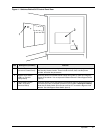
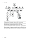
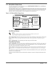
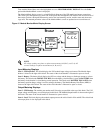
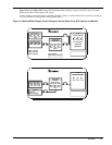
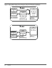
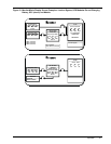
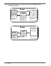
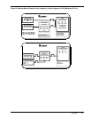
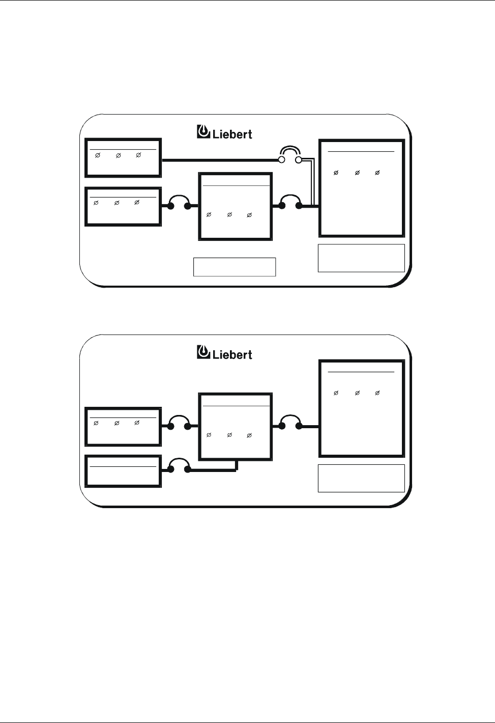
Figure 16 through Figure 20 illustrate how the Monitor/Mimic Display screens on the SCC and on a module
depict the power flow through the UPS system.
A three module system designed for redundant operation is shown. A multi-module UPS system may include up
to six (6) modules for each System Control Cabinet (SCC).
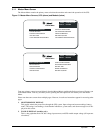
Figure 16 Monitor/Mimic Display Screen Examples: Normal Power Flow, SCC (above) and Module
UPSINPUT PWR
UPS RATINGS
A-B B-C C-A
BYPASSINPUT
A-B B-C C-A
LOAD
ABC
A-B B-C C-A
OK to Transfer
Static Switch Connected
OUTPUTVOLTAGE
ABC
627 KVA
/
502 KW
3OF 3MODULES
CONNECTED
REDUNDANT
A-B B-C C-A
MOD 1 ON LINE
MOD 2 ON LINE
MOD 3 ON LINE
480V
480V480V
480V
480V480V
480V
480V 480V
60.0 Hz
SCCB1600
60.0 Hz
755A
755A
755A
UPSINPUT PWR
BATTERY
VOLTS 540
AMPS15 CHARG
UPS RATINGS
A-B B-C C-A
OUTPUTVOLTAGE
LOAD
ABC
270 KVA
/
217 KW
A-B B-C C-A
480V 480V
480V
480V
480V 480V
60.0 Hz
350A
350A350A
410A
410A
RATED 400 KVA
410A
AP648-84