


Operation 29
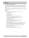
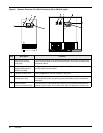
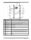
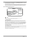
3.1.1 Master Menu Screen
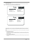
The Master Menu contains the primary menu selections that monitor and control the operation of the UPS.
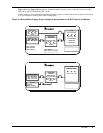
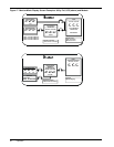
Figure 13 Master Menu Screens, SCC (above) and Module (below)
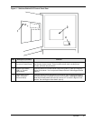
From any primary screen (accessed directly from the Master Menu), pushing the Select pad once will return you
to the Master Menu. From any secondary screen, pushing the Select pad twice will return you to the Master
Menu.
Please note that some screens have multiple pages. However, in each case instructions appear for accessing other
pages.
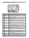
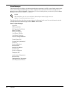
1. MONITOR/MIMIC DISPLAY.
This graphic mimics the power flow through the UPS system. Input voltage and current readings, battery
status, UPS ratings, load readings, circuit breaker indications, system status, and alarm messages are all dis-
played on this screen.
2. WALK-IN DISPLAY (modules only).
This is a bar graph that shows DC bus voltage, input currents, and UPS module output voltage (all in percent
of nominal).
CURSORUP
CURSORDOWN
CHOOSE
UP :
DOWN :
SELECT :
WALK-IN DISPLAY
STATUSREPORTS
SYSTEM CONFIGURATION
LIMIT SETTINGS
START-UP PROCEDURES
SHUTDOWN PROCEDURES
BATTERYTIME
METER CALIBRATION
BATTERYEQUALIZE
MONITOR/MIMIC DISPLAY
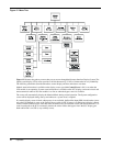
MASTER MENU
CURSOR UP
CURSOR DOWN
CHOOSE
UP :
DOWN :
SELECT :
STATUSREPORTS
SYSTEM CONFIGURATION
LIMIT SETTINGS
LOAD TRANSFER PROCEDURES
START-UP PROCEDURES
SHUTDOWN PROCEDURES
METERCALIBRATION
BATTERYEQUALIZE
CUSTOMERALARM DEFINITIONS
MONITOR/MIMICDISPLAY
MASTER MENU