


78 Operation
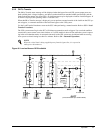
3.2 Modes of Operation
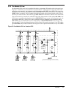
This section illustrates the flow of power through circuit breakers, switches, and UPS components during various
modes of operation. An SCCB with three modules is shown. The same modes of operation apply to all configu-
rations of the Liebert Series 600T UPS multi-module system. Highlighted (thick) lines in the diagrams indicate
power flow and power availability.
These illustrations show a three-breaker maintenance bypass because it is most commonly used. Your installa-
tion may have a two-breaker, three-breaker, or four-breaker maintenance bypass, or none at all.
These illustrations do not show an alternate power source (generator) and automatic transfer switch (external to
the UPS) that might be present at your installation.
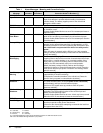
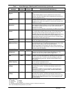
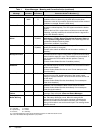
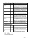
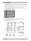
The following circuit breaker abbreviations are used:
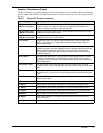
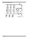
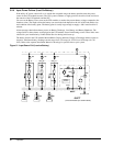
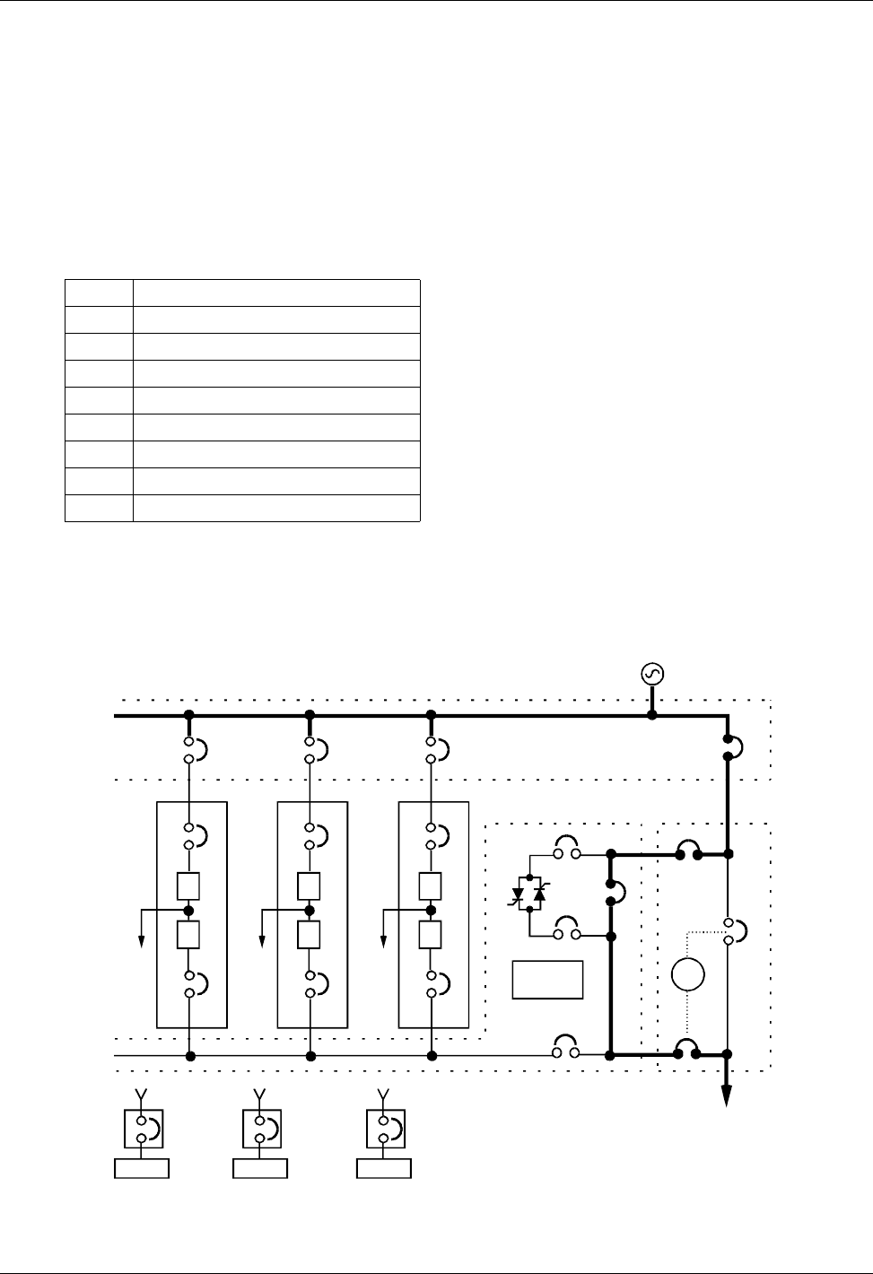
3.2.1 Load On Bypass
Load on Bypass, with the UPS not available, is shown in Figure 47. The UPS system could be in this mode of
operation during either initial start-up or UPS system shutdown and isolation for maintenance.
Figure 47 Load on Bypass (UPS Not Available)
BFB Bypass Feeder Breaker
BIB Bypass Input Breaker
CB1 Module Input Breaker
CB2 Module Output Breaker
MBB Maintenance Bypass Breaker
MBD Module Battery Disconnect
MIB Maintenance Isolation Breaker
RIB Rectifier Input Breaker
SBB System Bypass Breaker
I
R
#2UPS
CB1
CB2
I
R
#1UPS
CB1
System
Controls
I
R
#3UPS
CB1
CB2
RIB RIB
BIB
CB2
SKRU
RIB BFB
MIB
Output
SBB
SBS
MBB
SCCT
(can accommodate up to 6 UPS modules)
To CriticalLoad
Battery
MBD
SCCT
Battery
MBD
Battery
MBD