


Operation 25
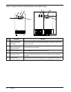
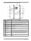
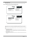
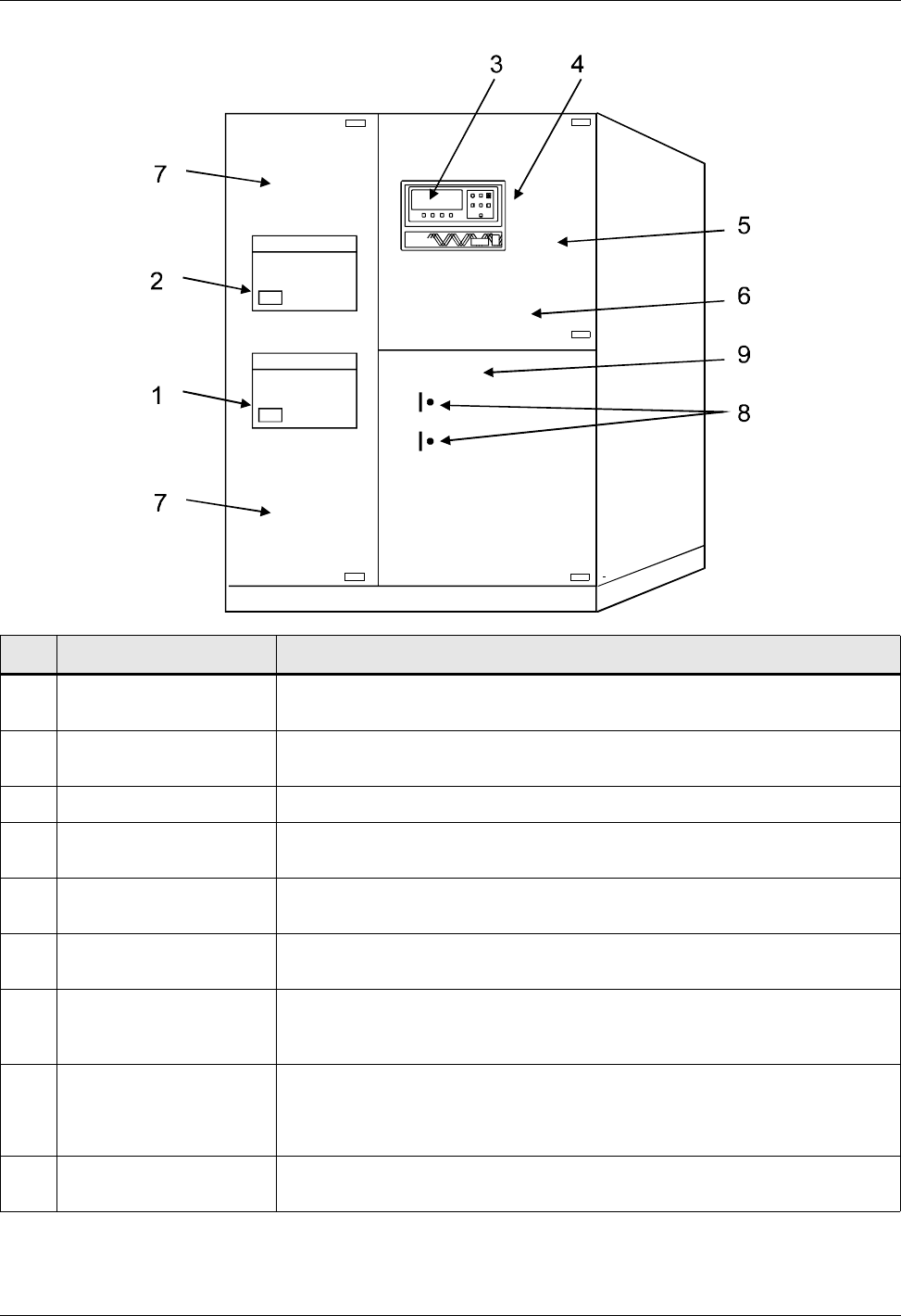
Figure 9 System Control Cabinet Operator Controls (SCCB Pictured)
Item Description Function
1UPSOutputCircuit
Breaker
This motorized circuit breaker connects the critical load to the UPS system output.
2 System Bypass Circuit
Breaker
This motorized circuit breaker connects the critical load to the bypass line.
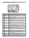
3 Operator Control Panel Refer to Figure 10 for controls available on this panel.
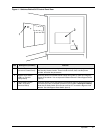
4 Interlock Button
(on rear of Control Panel)
Refer to Figure 11.
5 Close Bypass Switch
(behind door)
Refer to Figure 11.
6 Bypass Reset Switch
(behind door)
Refer to Figure 11.
7 Static Switch Disconnects
(behind door)
These manually operated switches disconnect the static switch from the bypass
line and from the critical load. They are normally ON (closed). Turn them OFF
(open) only to isolate (disconnect) the static switch for maintenance procedures.
8 Reset Switches (SW1) for
Static Switch Disconnects
(behind door)
Press these two switches before closing Static Switch Disconnects when
recovering from a shutdown that includes loss of Control Power. Green LED on
means Control Power is available. Red LED on means Reset Switch needs to be
pushed.
9 Control Power Disconnect
(behind door)
Normally ON. Turn OFF Control Power only when required for maintenance
procedures.