


Operation 59
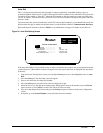
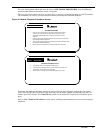
From the module Master Menu, move the highlighted cursor to START-UP PROCEDURES. Press the Select
pad and the module Start-Up Procedures screen is displayed.
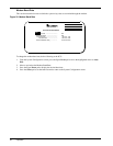
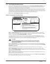
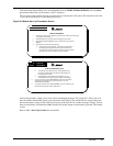
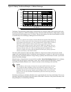
This two-page screen contains the steps you must follow to start-up each UPS system. The instructions are listed
so you can review them prior to performing the start-up.
Figure 38 Module Start- Up Procedures Screen
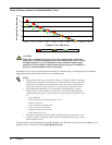
Prior to this procedure, supply power to the critical load through the bypass line (at the SCC). When you close
the UPS module input breaker, power is provided to the UPS rectifier. The module DC bus voltage ramps up to
the nominal battery voltage and the UPS inverter turns on when the DC bus reaches the proper voltage. You can
then close the battery circuit breaker (MBD) and the UPS module output circuitbreaker to place the UPS module
on-line.
Refer to 3.3.1 - Start-Up Procedure for more details.
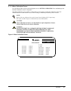
START-UP PROCEDURES
1. Verify that the control power is applied to the system control cabinet (check the display
on the system control cabinet).
2. Wait approximately two (2)minutes before attempting any other action .
3. Select "SYSTEM CONFIGURATION" screen to verify that the correct model is
displayed.
4. Select "WALK-IN" screen and do the following:
a) Close module input circuit breaker. Verify that the DC voltage bar on
the display begins to gradually move to the right and the AC input
current bars do not move to the right more than 10% (40% for modules
with input filters) afterthe transformer inrush has subsided.
NEXT PAGE
MASTER MENU
DOWN :
SELECT :
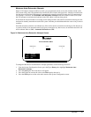
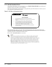
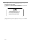
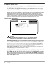
START-UP PROCEDURES (Cont'd)
b) Verify that the output voltage bar moves to the right after the DC
bus bar has reached the 90% point. Both bars should settle near
their respective 100%levels.
c) If anything happens on the display not mentioned in (a) or (b),
immediately open the module input circuit breaker and investigate.
5. If step 4 is successful, select "MONITOR/MIMIC" screen and verify module
DC bus and output voltages are at proper nominal level. If so, close
module battery circuit breaker.
6. If no alarms are present on the "MONITOR/MIMIC" screen, the module may be
placed online by closing the module output breaker.
FIRST PAGE
MASTER MENU
UP :
SELECT :