


74 Operation
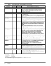
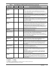
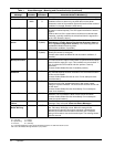
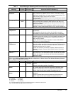
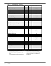
Table 2 Alarm Messages - Summary
Alarm Message MMU SCC Special Functions
Input Fail X — —
DC Ground Fault X — L, S
DC Capacitor Fuse Blown X — D, F, S
Battery CB Open X, R — S
Battery Discharging X, R R S
Low Battery Warning X, R R S
Low Battery Shutdown X — D, F, L, S
DC Over-Voltage Shutdown X — D, F, L, S
Load On Bypass — X, R —
Auto Transfer to Bypass — E D, F
Auto Retransfer Primed — X —
Manual Reset/Retransfer — X —
Static Switch Unable — X S
Bypass Not Available — X —
Bypass Phase Sequence Wrong — X —
Input Current Unbalanced E — —
Control Power Fail X, R X L, S
Output Over/Under Frequency — X L, S
Output Under-Voltage — X D, F, L, S
Output Over-Voltage — X D, F, L, S
Overload X X, R S
Overload Transfer — X D, F, L, S
Inverter Non-Synchronized X — —
Module N (1-6) Off Line R X D
Overload Shutdown X — D, F, L, S
Reverse Power X — D, F, L, S
Rectifier Fuse Blown X — D, F, S
Inverter Fault X — D, F, S
Hardware Shutdown X — D#
Emergency Off X X D*, F, S
Ambient Over-Temperature X, R R S
Blower Failed X — S
Equipment Over-Temperature X — S
Over-Temperature Timeout X — D, F
Load On UPS — R —
New Alarm R R —
Module Summary Alarm R X S
System Summary Alarm — R —
D = Auto-Dial initiated
D* = Auto-Dial initiated through Auto Transfer
to Bypass if load is on UPS
D# = Auto-Dial initiated through ModuleN (1-6)
off-line
E = message displayedon Status Report screens
F = freezes the History Status Report memory buffer
L = latches the displayed alarm message
R = Remote Alarm Contact (optional on MMU)
S = Summary Alarm (System or Module) initiated
X = message displayed on Monitor/Mimic screen
and audible alarm