


Theory of Operation 15
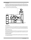
2.2 Detailed Component Descriptions
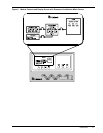
2.2.1 Controls
Hardware
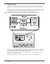
The Series 600T UPS Operator Interface Display System is designed to provide all of the information that is
required for the operation of each UPS cabinet (the System Control Cabinet and each module). The following is
a list of the hardware features:
1. The control logic performs automatic operations with minimal operator interface. The limited number of
manual controls are easy-to-use.
2. Each Series 600T UPS cabinet is equipped with an easy-to-read 640 x 200 pixel liquid crystal display (LCD)
screen. It presents information in a way that is easy to understand at an eye-level front panel location.
3. The display is controlled by a dedicated microprocessor with a non-volatile (EPROM) program and a
battery-backed event memory.
4. The Series 600T System Control Cabinet (SCC) has communication ports (terminal board connections) for:
a. Transmission of present status information to remote terminals via resident auto-dial communications
program and an external modem. This port also responds to inquiries of the UPS system status and
history from the remote terminal.
b. Reporting UPS system status and history information in response to inquiries from a local terminal (no
modem required).
c. Reporting to a local monitor the information requested from the local terminal.
d. Reporting information to a Liebert SiteScan central monitoring system.
e. Relaying selected alarm messages to a Liebert Remote Monitor Panel and to a separate terminal board
for customer use.
f. Relaying performance and status information to your network monitoring system via SNMP interface.
Firmware
The Operator Interface Display System software enables the operator to monitor the UPS system status, to con-
trol the power flow through the UPS, to monitor all of the meter readings, to execute the start-up, shutdown, and
the load transfer procedures, to access the event history files, and to make adjustments to the programmable
parameters. The following is a list of the firmware features:
1. The menu-driven software prompts the operator for input.
2. Step-by-step instructions assist the operator during start-up, shutdown, and load transfer procedures. This
helps to eliminate operator errors.
3. Graphics-based mimic diagrams illustrate circuit breaker status and the power flow through the UPS system.
4. The Present Status screen reports information about the system’s present status. The History Status screen
chronicles the events leading up to and immediately after a fault. The Event History screen lists all of the
alarm messages that have been logged over a period of time.
5. The Battery Cycle Monitor records information on up to 132 battery discharge events. Information includes
date, time, length of discharge, highest current demand, lowest battery voltage, and cumulative battery amp
hours discharged.
Refer to 3.0 - Operation for a description of the controls and indicators located on the Operator Control Panel.
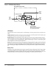
2.2.2 Rectifier/Charger
The UPS module rectifier/charger consists of an input circuit breaker, optional input isolation transformer, AC
current limiting circuit, battery equalize charge circuit, DC filter, battery charge current limiting circuit, and
bridge rectifiers.
Operation
The rectifier/charger converts the AC input power to DC power. This conversion is accomplished by 3-phase
bridge rectifiers using SCRs. All phases are individually fused. Reflected input current THD is less than 7% at
NOTE
All external communication devices are optional equipment.