


Installation & Operation Manual
20
2 General venting (continued)
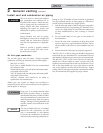
5. Dry fit vent or air piping to ensure proper fit up
before assembling any joint. The pipe should go
a third to two-thirds into the fitting to ensure
proper sealing after cement is applied.
6. Priming and Cementing:
a. Handle fittings and pipes carefully to prevent
contamination of surfaces.
b. Apply a liberal even coat of primer to the fitting
socket and to the pipe end to approximately 1/2"
beyond the socket depth.
c. Apply a second primer coat to the fitting
socket.
d. While primer is still wet, apply an even coat of
approved cement to the pipe equal to the
depth of the fitting socket along with an even
coat of approved cement to the fitting socket.
e. Apply a second coat of cement to the pipe.
f. While the cement is still wet, insert the pipe into
the fitting, if possible twist the pipe a 1/4 turn as
you insert it. NOTE: If voids are present,
sufficient cement was not applied and joint could
be defective.
g. Wipe excess cement from the joint removing
ring or beads as it will needlessly soften the
pipe.
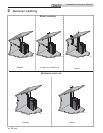
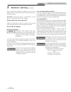
Table 2E PVC/CPVC Vent Pipe, and Fittings
Approved PVC/CPVC Vent Pipe and Fittings
Item Material Standard
Vent pipe
PVC Schedule 40, 80 ANSI/ASTM D1785
PVC - DWV ANSI/ASTM D2665
CPVC Schedule 40, 80 ANSI/ASTM F441
Vent fittings
PVC Schedule 40 ANSI/ASTM D2466
PVC Schedule 80 ANSI/ASTM D2467
CPVC Schedule 80 ANSI/ASTM F439
Pipe Cement /
Primer
PVC ANSI/ASTM D2564
CPVC ANSI/ASTM F493
NOTICE: DO NOT USE CELLULAR (FOAM) CORE PIPE
NOTE: In Canada, CPVC and PVC vent pipe, ttings and cement/
primer must be ULC-S636 certi ed.
1. Work from the boiler to vent or air termination. Do not
exceed the lengths given in this manual for the air or vent
piping.
2. Cut pipe to the required lengths and deburr the inside
and outside of the pipe ends.
3. Chamfer outside of each pipe end to ensure even
cement distribution when joining.
4. Clean all pipe ends and fittings using a clean dry rag.
(Moisture will retard curing and dirt or grease will prevent
adhesion.)
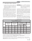
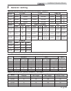
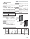
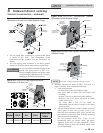
IMG01147
8" PVC PIPE
(FIELD SUPPLIED)
8" PVC COUPLING
(FIELD SUPPLIED)
8" CPVC PIPE
STARTER PIECE
(AVAILABLE FROM FACTORY
W/KIT #100267012)
8" PVC TO STAINLESS
ADAPTER (AVAILABLE FROM
FACTORY W/KIT #100267012)
NOTE: CPVC VENT OR STAINLESS STEEL
PIPE AND VENT FITTINGS MUST BE USED
IN CLOSET AND ALCOVE INSTALLATIONS.
Figure 2-3 Near Boiler PVC/CPVC Venting - Model 1251
- 2001 (Flue connections from the factory are sized for stainless
steel venting.)
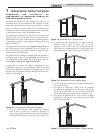
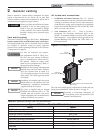
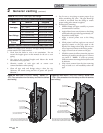
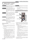
IMG01146
6" PVC PIPE
(FIELD SUPPLIED)
6" PVC COUPLING
(FIELD SUPPLIED)
6" CPVC PIPE
STARTER PIECE
(FACTORY SUPPLIED)
6" PVC TO STAINLESS ADAPTER
(FACTORY SUPPLIED)
NOTE: CPVC VENT OR STAINLESS STEEL
PIPE AND VENT FITTINGS MUST BE USED
IN CLOSET AND ALCOVE INSTALLATIONS.
Figure 2-2 Near Boiler PVC/CPVC Venting - Models 751 -
1001 (Flue connections from the factory are sized for stainless
steel venting.)