


35
Installation & Operation Manual
6 Gas connections
Connecting gas supply piping
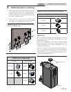
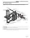
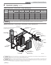
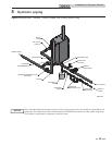
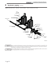
1. Refer to FIG. 6-1 to pipe gas to the boiler.
a. Install ground joint union for servicing, when
required.
b. In Canada – When using manual main shutoff
valves, it must be identified by the installer.
Do not check for gas leaks with an open
flame – use the bubble test. Failure to
use the bubble test or check for gas leaks
can cause severe personal injury, death, or
substantial property damage.
3. Purge all air from the gas supply piping.
4. Before placing the boiler in operation, check the boiler
and its gas connection for leaks.
a. The appliance must be disconnected from the gas
supply piping system during any pressure testing of
that system at a test pressure in excess of 1/2 PSIG
(3.5 kPa).
b. The appliance must be isolated from the gas supply
piping system by closing a manual shutoff valve
during any pressure testing of the gas supply piping
system at test pressures equal to or less than 1/2 PSIG
(3.5 kPa).
c. The appliance and its gas connection must be leak
tested before placing it in operation.
ƽ WARNING
5. Use pipe sealing compound compatible with propane
gases. Apply sparingly only to male threads of the pipe
joints so that pipe dope does not block gas flow.
Failure to apply pipe sealing compound as
detailed in this manual can result in severe
personal injury, death, or substantial
property damage.
ƽ WARNING
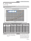
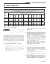
Model Gas Inlet Size
FB0751 1 1/4"
FB1001 1 1/4"
FB1251 1 1/4"
FB1501 1 1/2"
FB1751 1 1/2"
FB2001 1 1/2"
Table 6A Gas Inlet Size
For dual fuel models, reference the Crest
Dual Fuel Supplemental Manual.
NOTICE
Gas supply
1. It is recommended to install one (1) gas regulator for each
Crest boiler.
2. Gas regulators should be installed in a horizontal
orientation unless otherwise recommended by the
regulator manufacturer.
3. It is recommended to install a filter at the inlet of a gas
regulator to prevent debris from entering the regulator.
4. Gas regulators should be installed the greater of either 20
inches or 10 pipe diameters from the nearest fitting, elbow,
or valve to the outlet of the regulator.
5. It is recommended that the gas regulator outlet size match
the gas inlet size of the boiler and to not change the pipe
size between them. If the pipe diameter must be increased,
a bell reducer type fitting should be located at the regulator
outlet and the boiler inlet, maintaining the distance
indicated in Step 4.
6. Gas regulators must be properly vented to ensure proper
function:
a. Vent pipe must be no smaller than the regulator vent
connection size.
b. Each regulator must have a separate vent line.
c. Vent lines must not be combined together or with any
other equipment that also requires atmospheric vents.
d. Excessive gas regulator vent length will detrimentally
affect regulator performance:
• Gas regulators must be properly vented according to
the regulator manufacturer’s instructions.
• It is recommended that regulator vent length not
exceed 15 equivalent feet (4.5 m).
• When regulator vent must exceed 15 equivalent feet, it
is recommended to use a ventless regulator equipped
with a vent limiter.
• If a ventless regulator cannot be utilized, it is
recommended to increase vent diameter by one pipe
size after the initial 15 equivalent feet and every additional
10 equivalent feet.
e. Proper measures must be taken to prevent water,
snow, insects, or other debris from obstructing the vent.
Ensure that the high gas pressure regulator
is at least 10 feet (3 m) upstream of the
appliance.
NOTICE
2. Support piping with hangers, not by the boiler or its
accessories.
The gas valve and blower will not support
the weight of the piping. Do not attempt
to support the weight of the piping with
the boiler or its accessories. Failure to
comply could result in severe personal
injury, death, or substantial property
damage.
ƽ WARNING
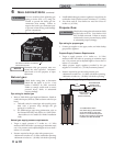
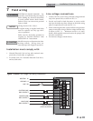
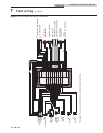
Figure 6-1 Gas Supply Piping
SEDIMENT TRAP/
DRIP LEG CLEAN OUT
(FACTORY SUPPLIED)
MANUAL SHUTOFF
VALVE
(FACTORY SUPPLIED)
GAS SUPPLY
UNION
(FACTORY
SUPPLIED)