


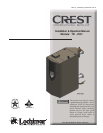

Installation & Operation Manual
4
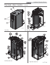
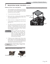
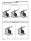
The Crest - How it works...
1. Front access panels
Provides access to the controls compartment.
2. Top access panel
Provides access to the burner compartment.
3. Air pressure switch
The air pressure switch detects blocked flue/vent conditions.
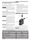
4. Blower
The blower pulls in air and gas through the venturi (item
34). Air and gas mix inside the blower and is pushed into the
burner, where they burn inside the combustion chamber.
5. Boiler drain connection
Location from which the heat exchanger can be drained.
6. Boiler inlet temperature sensor
The boiler inlet temperature sensor monitors system return
water temperature. If selected as the controlling sensor,
the control module will adjust the boiler firing rate so the inlet
temperature matches the set point.
7. Boiler outlet temperature sensor
The boiler outlet temperature sensor monitors boiler outlet
water temperature. If selected as the controlling sensor,
the control module will adjust the boiler firing rate so the outlet
temperature matches the set point.
8. Burner (not shown)
Single chamber design with a stress free metal fiber outer mesh
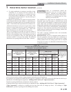
and durable stainless steel structure. Provides firing rates up to
15:1 turndown (Model 751), 20:1 turndown (Models 1001 -
1251) and 25:1 turndown (Models 1501 - 2001).
9. Condensate drain connection
The condensate drain connection provides a connection
point to install a condensate drain line using flexible hose
provided.
10. Control module (on control panel assembly)
The control module responds to internal and external signals
and controls the blower, gas valves, and pump(s), depending on
the application, to meet the heating demand.
11. Electronic display
Digital controls with SMART TOUCH screen technology, full
color display, and an 8" user interface screen.
12. Flame inspection window
Two large high temperature quartz observation windows
provide views of the burner surface during firing.
13. Dual flame sensors (not shown)
Two flame sensors are provided to monitor the main burner
and transition flame.
14. Flue temperature sensor
The flue sensor monitors flue gas temperature. The control
module will modulate or shut the boiler down if the flue gas
temperature gets too high.
15. Gas connection pipe
The gas connection pipe is a threaded black iron pipe
connection (see Gas Connections Section for specific model
pipe size requirements). This pipe should be connected to the
incoming gas supply to deliver gas to the boiler.
16. Gas shutoff valve (inside unit)
The manual gas shutoff valve is used to isolate the boiler gas
train from the gas supply.
17. Gas valves
The gas valves sense the negative pressure created by the
blower, allowing gas to flow only if the gas valves are powered
and combustion air is flowing.
18. Condensate trap
The condensate trap is sized for a 1" PVC outlet connection
pipe.
19. High limit devices (primary and backup)
The high limit devices are used to monitor the outlet water
temperature - if either device senses the water temperature
exceeding the predetermined setting, the boiler will shut down.
20. Ignition electrode
An electrical spark across the electrodes will ignite the burner.
21. Line voltage junction box
The line voltage junction box contains the connection points for
the line voltage power to the boiler (and pumps if used).
22. Line voltage wiring connections (knockouts)
Conduit connection points for the high voltage junction box.
23. Low gas pressure switch
Monitors gas supply pressure to the boiler and shuts the boiler
down in the event a low gas pressure condition occurs.
24. High gas pressure switch
Monitors gas supply pressure to the boiler and shuts the boiler
down in the event a high gas pressure condition occurs.
25. Low voltage connection board(s)
Connection boards used to connect external low voltage devices.
26. Low voltage wiring connections (knockouts)
Conduit connection points for the low voltage connection boards.
27. Low water cutoff probe (LWCO - not shown)
Ensures adequate water is supplied to the boiler. In the event of
inadequate water levels, the boiler will shut down.
28. Power switch
The On/Off power switch provides the ability to turn line voltage
power to the boiler on and off.
29. Relief valve
The safety relief valve protects the heat exchanger from an over
pressure condition. The boiler comes with a 50 PSI relief valve as
standard equipment. Optional settings are available.
30. Reset switch
Reset switch for the low water cutoff. Hold the switch for 10
seconds to reset.
31. Test switch
The test switch permits manual triggering of the LWCO
safety circuit to test the contacts and evaluate the integrity of the
circuit. Hold the switch for 10 seconds to test.
32. Firetube heat exchanger
High grade stainless steel WAVE
TM
firetube design that extracts
heat from flue gases and transfers it directly into boiler water.
33. Temperature and pressure gauge
Monitors the outlet temperature of the boiler as well as the system
water pressure.
34. Venturi
The venturi controls air and gas flow into the burner.
35. Water inlet
A 3" (Models 751 - 1251) or 4” (Models 1501 - 2001)
ANSI flange connects the return water from the system to the
heat exchanger.
36. Water outlet
A 3" (Models 751 - 1251) or 4" (Models 1501 - 2001)ANSI flange
connects the hot water supply from the boiler to the system.
37. Ignition transformer
The transformer provides voltage to the ignition electrode (item
20).
38. Air arm temperature sensor (not shown)
Monitors fuel-air delivery temperature to the burner.
39. Air inlet cover (shipped loose)
Used with room air for combustion and to prevent debris from
entering the boiler.
40. Fuses
A low resistance resistor that acts as a sacrificial device to provide
over current protection, of either the load or source circuit.
41. Air metering valve
The air metering valve is used to control the amount of air used
when firing.
42. Air metering valve air pressure switch
The air metering valve air pressure switch is used to ensure the air
metering valve is open when firing gas valve 2.