


34
Installation & Operation Manual
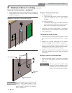
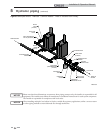
5 Hydronic piping (continued)
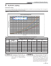
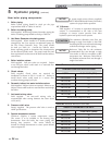
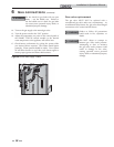
Please note that these illustrations are meant to show piping concepts only, the installer is responsible for all
equipment. The installer must follow all manufacturer’s installation instructions for each system component.
The installer is responsible for compliance with local codes.
NOTICE
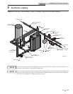
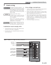
Y-STRAINER
(RECOMMENDED)
(TYPICAL)
RELIEF
VALVE
(TYPICAL)
AIR SEPERATOR
DRAIN PORT
(TYPICAL)
SYSTEM
CIRCULATOR
BACK FLOW
PREVENTER
PRESSURE
REDUCING VALVE
PRESSURE
GAUGE
EXPANSION
TANK
FROM SYSTEM
TO SYSTEM
MAKE UP
WATER
BOILER
DRAIN
(TYPICAL)
SYSTEM RETURN
SENSOR
SYSTEM SUPPLY
SENSOR
IMG01039
ISOLATION
VALVE
2-WAY MOTORIZED
VALVE (OPTIONAL)
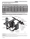
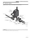
Figure 5-5 Multiple Boilers - Alternate - Common Header - Fixed or Variable Flow Primary
When installing multiple Crest boilers in fixed or variable flow primary applications, utilize a reverse-return
or other piping method to ensure balanced flow through each boiler.
NOTICE