


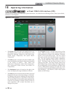

10 Operating information
54
Installation & Operation Manual
Gradient limiting
If during operation of the boiler the outlet water temperature
is rising too quickly, the control will reduce the firing rate to
its lowest setting.
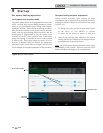
Outdoor air reset
If an outdoor air sensor is connected, the control module
will calculate the set point based on the programmed reset
curve. The installer can change the slope of the reset curve
by several adjustable parameters. The user can limit the
maximum set point for the system using the space heating
set point.
Boost function
If outdoor air reset is active, the boost temperature is not
0, a space heating demand has been active continuously for
a set period of time (time adjustable by installer) and there
has been no HW demands, the control will increase the set
point by a fixed number of degrees (adjustable by installer).
This process will continue until the space heating demand
ends, the set point reaches the programmed set point or a
maximum of 20 increases has occurred. Once the system
heat demand is satisfied, the set point will revert to the value
determined by the reset curve.
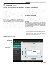
Night setback
The controller may be programmed to reduce the space
heating set point and/or Hot Water Generator set point for
each demand during a certain time each day. A start and
stop time for each demand can be programmed for each day
of the week. The controller can be programmed to reduce
the tank set point as well. A different set of start and stop
times can be programmed each day of the week.
Flame current support
To prevent nuisance shutdowns when the boiler is firing at
minimum rates, the control will increase the firing rate when
the flame signal drops too low.
ModBus / BACnet
The Crest boiler can be connected to and controlled by a
Building Automation System through a ModBus or BACnet
interface. Connect the A and B wires to the A and B
terminals. If connecting another cable (in a daisy chain),
connect the shield wire of the first cable to one of the shield
terminals, and the shield wire of the second cable to the other
shield terminal. If it is desired to ground the cable shield
at the heater, connect the shield wire to one of the shield
terminals, and install a jumper across the two (2) terminals
in connector X5 on the ModBus / BACnet interface board.
0-10V Rate output
A 0-10V signal which indicates the firing rate of the heater
is available. This output may be connected to a Building
Management System (BMS) to allow it to monitor the actual
firing rate. Connect the - terminal to the COM or - terminal
on the BMS, and connect the + terminal to the 0 - 10V or +
terminal on the BMS.
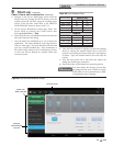
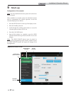
Ramp Delay
For systems with lower flow, the SMART TOUCH can limit
the firing rate (when enabled) when a space heating call for
heat starts, or when switching from a DHW call for heat to a
space heating call for heat. There are six (6) limits that can be
programmed, as well as six (6) time intervals corresponding to
each limit. The sixth limit will also limit the firing rate for the
rest of the call for heat.
Protection features
Outlet temperature, flue temperature, and temperature
rise limiting
The outlet water temperature is monitored by the boiler outlet
temperature sensor. When the outlet temperature exceeds
185°F, the unit will reduce the fan speed. If the outlet water
temperature exceeds 195°F (90°C) the control will shut the unit
down until the minimum off time has expired and the outlet
drops 10°F (5.5°C).
The control module monitors the flue temperature by a sensor
located in the flue exhaust. If the flue temperature exceeds
215°F (101°C) the control will reduce the maximum fan speed.
If the flue temperature exceeds 250°F (121°C) the control will
shut the unit down. The unit will restart automatically once
the flue temperature drops 50°F (27°C) and the minimum off
time has expired.
The control monitors the temperature difference between
the inlet and the outlet sensor. If this difference exceeds
70°F (21°C) the control will reduce the fan speed. If the
temperature difference exceeds 80°F (27°C) the control will
shut the unit down. The unit will restart automatically once
the temperature difference has dropped below 50°F (28°C) and
the minimum off time has expired.
Freeze protection
DO NOT install the boiler in a room likely to freeze.
The following integral feature of the SMART TOUCH control
module provides some protection for the boiler only -- not for
the system.
• The SMART TOUCH control module provides
freeze-up protection as follows when the boiler
water temperature drops below 45°F (7°C):
• Below 45°F (7°C), the boiler and system pumps (if
enabled) operate constantly.
• Below 37°F (3°C), the boiler turns on.
• Boiler and pumps turn off if boiler water
temperature rises above 43°F (6°C).
This feature of the SMART TOUCH control
module does not eliminate the possibility
of freezing. The installation must still
use recognized design, installation and
maintenance practice to prevent freeze
potential for the boiler and system.
ƽ CAUTION