


49
Installation & Operation Manual
9 Start-up (continued)
Check flame and combustion (continued)
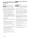
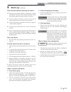
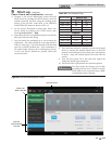
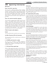
4. Navigate to the Service Maintenance Screen from the
Home Screen by pressing the SETUP button, enter the
installer password, and then using the scrolling menu
feature on the left side, scroll down to the SERVICE
MAINTENANCE button as shown in FIG. 9-3.
5. On the Service Maintenance Screen place heater into
Service Mode by selecting the START button, then
selecting Set Gas Valve 1 - High.
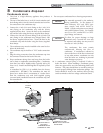
6. Insert the probe from a combustion analyzer into the hole
left by the removal of the fitting.
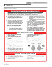
7. Once the boiler has modulated up to rate, measure the
combustion. The values should be in the range listed in
Table 9A (this page). CO levels should be less than 200
ppm for a properly installed unit. If the combustion is
not within range reference the Troubleshooting Section
in the Crest Service Manual for possible causes and
corrective actions.
Table 9A Flue Products Chart
8. Once the heater analysis is complete, test the safety shutoff
device by turning the manual shutoff valve to the OFF
position and ensuring the heater shuts down and registers
an alarm. Open the manual shutoff valve and reset the
control.
9. Turn the main power off to the boiler and replace the
fitting into the flue pipe connection.
10. Ensure the boiler is placed back into normal operation.
You must replace the fitting to prevent flue
gas spillage into the room. Failure to comply
could result in severe personal injury, death,
or substantial property damage.
ƽ WARNING
Flue Products
Natural Gas
Gas Valve
CO
2
(%) O
2
(%)
Valve 1 High 9.2 4.6
Valve 1 Low 9.0 4.9
Valve 2 High 9.3 4.4
Valve 2 Low 8.7 5.5
Propane
Valve 1 High 11.0 4.1
Valve 1 Low 10.0 5.6
Valve 2 High 11.1 4.0
Valve 2 Low 10.7 4.6
**All set points should be within +/- 0.2%**
SCROLLING
MENU FEATURE
SETUP BUTTON
SERVICE
MAINTENANCE
BUTTON
Figure 9-3 Service Maintenance Screen