


62
Installation & Operation Manual
11 Maintenance
Check flame signal
1. At high fire of each combustion system, the flame signal
shown on the display should be at least 10 microamps.
2. A lower flame signal may indicate a fouled or damaged
flame sense electrode. If cleaning the flame sense electrodes
does not improve, ground wiring is in good condition, and
ground continuity is satisfactory, replace the flame sense
electrode.
3. See Section 3 - Troubleshooting in the Crest Service Manual
for other procedures to deal with low flame signal.
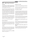
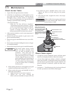
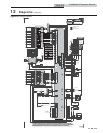
GAS/AIR MANIFOLD GASKET
BURNER
BURNER GASKET
GAS/AIR MANIFOLD
GAS/AIR MANIFOLD GASKET
BURNER TOP PLATE ASSEMBL
Y
FIBERBOARD
LOCHINVAR LOGO
GAS/AIR MANIFOLD COVER
NOTE: Be sure to pay close
attention to the Lochinvar logo.
A
lign the logo with the Lochinvar
logo on the gas/air manifold to
ensure proper assembly.
Pay close attention to the bolt
pattern, as the gas/air manifold
assembly can only be installed
one way.
DIR #2000508208
Figure 11-2 Burner Assembly
Check burner flame
1. Inspect flame through observation windows.
2. If the flame is unsatisfactory at either high fire or low
fire, remove and clean the burner. Clean the burner
thoroughly using a vacuum cleaner or compressed
air. Do not use compressed air to clean the burner if
cleaning is performed inside a building.
• Shut down the boiler:
- Follow the “To Turn Off Gas to Appliance”
instructions for the boiler in Section 9 - Startup
of the Crest Installation and Operation Manual.
- Do not drain the boiler unless it will be
exposed to freezing temperatures. If using
freeze prevention fluid in system, do not drain.
3. Allow time for the boiler to cool to room temperature if
it has been firing.
4. Remove the top access panel(s) to gain access to the
gas/air manifold assembly.
5. Remove the gas/air manifold burner access cover (FIG.
11-2).
6. Remove the nuts/washers holding the burner to the gas/
air manifold assembly.
7. Remove the burner from the gas/air manifold assembly.
NOTICE
The burner gasket, burner, burner
baffle, and gas/air manifold access
cover can only be installed in one
orientation. All of these parts will
have to be re-installed correctly. To
ensure all of these parts are re-installed
correctly, align the logo on top of the
gas/air manifold cover with the logo on
the gas/air manifold as shown in FIG.
11-2. Be certain to pay close attention
to the bolt pattern when re-installing
the above parts.
Failure to follow the torqueing specifications
listed in this manual could result in severe
personal injury or death.
ƽ WARNING
10. Re-install the gas/air manifold burner access cover.
Tighten 3/8" nuts to 8 ft.-lbs. using the star pattern
sequence.
11. After firing the unit, re-tighten the nuts to the torque
specifications.
8. When replacing the burner, ensure gaskets are in good
condition and positioned correctly (FIG. 11-2).
9. When securing the burner and manifold, be sure to
tighten the nuts as follows:
a. Tighten the nuts in a star pattern sequence.
b. Tighten the 7/16" nuts, securing the
burner to the cast manifold to a torque of 8 ft.-lbs.