


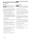

37
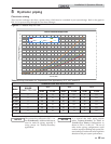
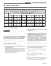
Table 6B Natural Gas Pipe Size Chart
The gas piping must be sized for the proper flow and length of
pipe, to avoid excessive pressure drop. Both the gas meter and
the gas regulator must be properly sized for the total gas load.
If gas pressure drops more than 1 inch w.c. (249 Pa) between
maximum and minimum input rate, the meter, regulator, or gas
line may be undersized or in need of service. Perform the steps
below when checking inlet gas supply:
1. Turn the main power switch to the “OFF” position.
2. Shut off gas supply at the manual gas valve in the gas
piping to the appliance.
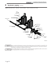
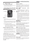
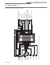
3. Remove the 1/8" pipe plug on the flange to the factory
supplied gas shutoff valve and install a suitable 1/8"
fitting (field supplied) for the manometer tubing. Place the
tubing of the manometer over the tap once the 1/8"
fitting is installed as shown in FIG. 6-4.
4. Slowly turn on the gas supply at the factory installed
manual gas valve.
5. Turn the power switch to the “ON” position.
6. Adjust the temperature set point on the control panel of
the SMART TOUCH control module to call for heat or
utilize Service Mode, see page 50 of this manual.
7. Observe the gas pressure with the burner
operating at 100% of rated input. Without turning
off the boiler, reduce the burner to the minimum input
rate and observe the gas pressure with the burner at
the minimum input rate. Percent of burner input will be
displayed on the Modulation Screen.
8. Ensure inlet pressure is within specified range.
Minimum and maximum gas supply pressures are
specified in this section of the manual.
9. If gas supply pressure is within normal range and no
adjustments are needed, proceed on to Step 11.
10. If the gas pressure is out of range, contact the gas utility,
gas supplier, qualified installer or service agency to
determine the necessary steps to provide proper gas
pressure to the control.
11. Turn the power switch to the “OFF” position.
12. Shut off the gas supply at the manual gas valve in the gas
piping to the appliance.
13. Remove the manometer from the pressure tap on top of
the gas valve. Remove the 1/8" (3 mm) field supplied
fitting and reinstall the pipe plug removed in Step 3.
DO NOT adjust or attempt to measure gas
valve outlet pressure. Attempting to alter
or measure the gas valve outlet pressure
could result in damage to the valve, causing
potential severe personal injury, death, or
substantial property damage.
ƽ WARNING
TABLE - 6B
Capacity of Schedule 40 Metallic Pipe in Cubic Feet of Natural Gas Per Hour
(based on .60 specific gravity, 0.30" w.c. pressure drop)
Pipe
Size
(Inches)
Length of Pipe in Straight Feet
10 20 30 40 50 60 70 80 90 100 125 150 175 200
1 1/4 1,060 726 583 499 442 400 368 343 322 304 269 244 224 209
1 1/2 1,580 1,090 873 747 662 600 552 514 482 455 403 366 336 313
2 3,050 2,090 1,680 1,440 1,280 1,160 1,060 989 928 877 777 704 648 602
2 1/2 4,860 3,340 2,680 2,290 2,030 1,840 1,690 1,580 1,480 1,400 1,240 1,120 1,030 960
3 8,580 5,900 4,740 4,050 3,590 3,260 3,000 2,790 2,610 2,470 2,190 1,980 1,820 1,700
4 17,500 12,000 9,660 8,270 7,330 6,640 6,110 5,680 5,330 5,040 4,460 4,050 3,720 3,460
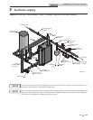
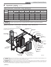
Check inlet gas supply
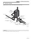
6 Gas connections
Installation & Operation Manual