


32
Installation & Operation Manual
5 Hydronic piping (continued)
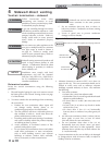
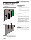
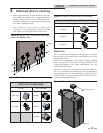
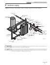
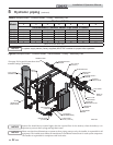
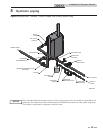
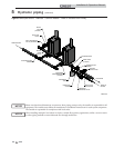
Please note that these illustrations are meant to show piping concepts only, the installer is responsible for all
equipment. The installer must follow all manufacturer’s installation instructions for each system component.
The installer is responsible for compliance with local codes.
NOTICE
HOT WATER
GENERATOR
WATER
GENERATOR
CIRCULATOR
BOILER PUMP
(TYPICAL)
FLOW CHECK
VALVE (TYPICAL)
Y-STRAINER
(RECOMMENDED)
RELIEF
VALVE
BALL VALVE
(TYPICAL)
AIR SEPERATOR
DRAIN PORT
(TYPICAL)
SYSTEM
CIRCULATOR
BACK FLOW
PREVENTER
PRESSURE
REDUCING VALVE
PRESSURE
GAUGE
EXPANSION
TANK
FROM SYSTEM
TO SYSTEM
MAKE UP
WATER
BOILER DRAIN
(TYPICAL)
SYSTEM RETURN
SENSOR
SYSTEM SUPPLY
SENSOR
IMG01037
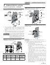
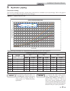
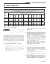
Figure 5-3 Multiple Boilers - Common Header - Recommended - Primary / Secondary Flow
Model
Number of Units
234567 8
Recommended Common Header Pipe Sizes in Inches
FB 0751
445566 7
FB 1001
455677 8
FB 1251
556778 10
FB 1501
567781010
FB 1751
5 6 7 8 10 10 10
FB 2001
6 6 8 8 10 10 12
NOTICE
A system supply sensor (factory supplied) MUST BE installed for proper boiler operation.
Table 5C Multiple Boilers - Common Header - Primary / Secondary Flow
System flow should always remain higher than the required flow for the boiler(s) when the boiler(s) is in
operation to prevent short cycling and high limit issues.
NOTICE
[Based on a boiler ΔT of 30°F.]
*
* See page 19 for special instructions when
common venting Crest boilers.