


Installation & Operation Manual
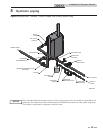
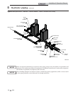
5 Hydronic piping
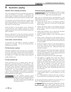
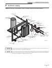
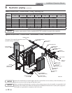
It is required that boiler piping systems
utilize Primary/Secondary or Fixed or
Variable Flow Primary configurations as
shown in FIG.’s 5-2 thru 5-5. The use of
other boiler piping configurations could
result in improper building and system flow
rates leading to inadvertent boiler high limit
shutdowns and poor system performance.
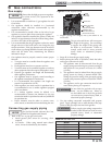
NOTICE
The pressure drop reflected in FIG. 5-1 is
for the boiler only. Additional allowances
must be made for piping, especially if
sizing pumps for Primary/Secondary
applications.
NOTICE
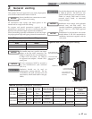
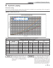
TEMPERATURE RISE APPLICATIONS
Model
BOILER
CONNECTION SIZE
20°F 40°F 60°F
GPM FT/HD GPM FT/HD GPM FT/HD
FB 0751 3" 72 1.5 36 0.5 24 0.2
FB 1001 3" 96 2.1 48 0.6 32 0.3
FB 1251 3" 120 3.0 60 0.9 40 0.4
FB 1501 4" 144 3.1 72 0.9 48 0.5
FB 1751 4" 168 3.7 84 1.1 56 0.5
FB 2001 4" 192 4.3 96 1.3 64 0.6
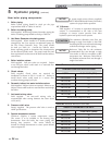
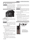
0
1
2
3
4
5
6
7
8
9
10
11
12
13
14
15
16
17
18
19
20
21
22
23
24
25
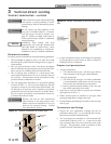
0 20 40 60 80 100 120 140 160 180 200 220 240 260 280 300 320 340 360
Pressure Drop (Feet of Head)
Flow Rate (GPM)
CREST Pressure Drop Curve
FB2001 FB1751 FB1501
FB1251 FB1001 FB7 51
Figure 5-1 Pressure Drop vs. Flow
Table 5A Sizing Information for Temperature Rise Applications_20°F, 40°F and 60°F
29
Circulator sizing
The Crest heat exchanger does have a pressure drop, which must be considered in your system design. Refer to the graph in
FIG. 5-1 for pressure drop through the Crest heat exchanger.
[Crest models are based on 96% AHRI Effi ciency]