


7
For complete instructions on setting up a new NMEA 2000 network or
expanding an existing one, see the other document packed with your
gauge, "Setup and Installation of NMEA 2000 Networks, General
Information" part number 988-0154-172. If that document is missing, it
can be downloaded free from the Lowrance web site.
Network Nodes
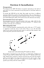
A network bus is built of network nodes spread along a backbone.
Network nodes are made by fitting T-shaped connectors into the
backbone (using the sockets on the sides), and attaching a display unit or
sensor at the bottom of the "T."
Using our telephone example, the T connectors are similar to telephone
jacks. The backbone is like the phone wiring running through a house.
Phones in a house must be connected to each other to communicate, and
in the same way only sensors and display units plugged into the NMEA
network can share information.
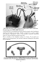
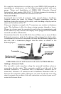
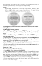
Connections found in the middle of the bus will have one or more of these
T-shaped connectors with the backbone cables plugged into both sides.
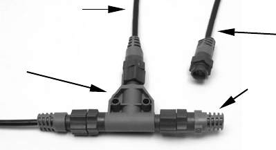
Connections at the end of a network will have the backbone plugged into
one side, and a terminator plugged into the other, as shown in the
following figure.
NMEA 2000 network node located at the end of a NMEA 2000 bus.
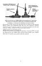
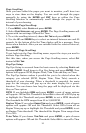
Adding a Network Node
You can add a node anywhere along the network backbone where a
connection already exists. This connection could be at the end of the
network (between a T connector and a terminator), between two T
connectors, between a T connector and a backbone extension cable, or
between two extension cables. Wherever you want to add the new node,
simply separate the sockets of the old connection and attach your new T
connector between them.
Backbone cable
(to rest of bus)
LEI or Lowrance
device needs an
open T.
Terminator at
the very end
of the bus
Cable from
sensor or
display unit
T connector