


Page 8 LSI Corporation | September 2010
LSISAS6160 SAS Switch User GuideChapter 1: Overview
| Serial Attached SCSI and the SAS6160 Switch
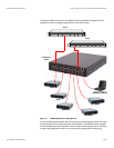
You can connect multiple SAS6160 switches in various topologies to provide failover
support and to increase the number of connected devices in the SAS domain. The
theoretical upper limit of SAS devices in a domain is 16,000. Each SAS6160 switch can
handle 1000 SAS addresses.
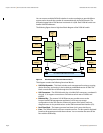
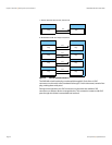
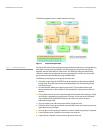
The following figure shows a high-level block diagram of the SAS6160 switch.
Figure 3: Block Diagram of the LSISAS6160 Switch
This diagram contains the following functional blocks:
SAS2X36 Expander – This block includes such management functions as routing,
device discovery, and zoning. It also includes an embedded version of SDM. This
block controls the flow of data through the SAS connectors.
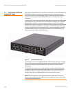
SAS Connectors – The SAS6160 switch has 16 x4 Mini SAS connectors, numbered 0
through 15. It supports connection to SAS devices at link rates of 3.0Gb/s and
6.0Gb/s.
Ethernet Phy – The external 10/100 Ethernet port provides access to the
browser-based SDM management application, which sets up storage
configurations in the SAS domain, monitors the status of the switch, and runs
diagnostic tests. It also provides access to the SDM command line interface (CLI).
Real Time Clock – The battery-powered real-time clock is set at the factory.
Fans – The SAS6160 switch enclosure contains two fans. The fan speed is regulated
based on the temperature inside the enclosure. You can monitor the status of the
fans with the SDM utility.
SAS2x36
Expander
Master
SAS2x36
Expander
Slave
Dual Port
Memory
32 SAS Lanes 32 SAS Lanes
16 x4 External Mini SAS Connectors
4 SAS Lanes (for failover)
Flash
Memory
Fan Control
RTC
Temp
Sensor
Ethernet
Phy
PBSRAM
Memory
Flash
Memory
Fan Control
PBSRAM
Memory
Temp
Sensor
x4 x4
x2 x2
x2x2