


6 Introduction
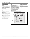
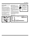
operation in on-line
mode
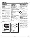
normal operation
Normal AC source power is available (see
figure 5).
■ lights 1 , 4 and 5 shine green on
the control panel;
■ the power necessary for the load is pro-
vided by the normal AC source (1) through
the rectifier/charger (A) and the inverter
(B);
■ the rectifier/charger (A) also supplies
the power to float charge and recharge the
battery if any.
The rectifier/charger output voltage (DC) is
regulated to supply:
❏ the float-charging or the recharging volt-
age for vented lead-acid or Ni/Cd batter-
ies,
❏ a single charge voltage for sealed lead-
acid batteries.
The voltages depend on the number of
battery cells and the battery manufacturer.
Factory set, they may also be adjusted by
after-sales support technicians.
An electronic board continuously mea-
sures the battery temperature and auto-
matically adjusts the voltages.
Note:
In parallel Galaxy PW™ systems, the
power drawn by the load is equally shared
between the different units.
Fig. 5
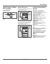
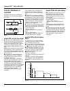
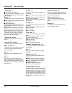
operation with the normal AC
source down
See figure 6.
In the event of a normal AC source failure
or voltage outside specified tolerances of
±10% in amplitude (±15% optionally), the
rectifier/charger (A) stops and the battery
(D) supplies the necessary backup power
to the load via the inverter (B). The bat-
tery, float-connected between the rectifi-
er/charger and the inverter, discharges
during this operating mode.
Lights 2 , 4 and 5 shine green.
The user is warned of battery operation by
the slow beeping of the buzzer 6 (see
figure 16) and the message "LOAD PRO-
TECTED, BATTERY DISCHARGING", fol-
lowed by the remaining backup time and
the percent load.
This information is also available via volt-
free changeover contacts for remote con-
trol devices.
Fig. 6
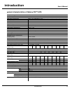
battery time
The available battery time during a normal
AC source outage depends on the:
■ rated capacity of the battery;
■ power consumed by the load;
■ temperature of the battery;
■ age of the battery.
The specified battery time corresponds to
a minimum duration at full rated load.
The actual backup time can therefore be
greater if the system operates below its
full rated load during the normal AC
source outage. Operation on battery
power can be extended beyond the speci-
fied time by reducing the load power con-
sumption (by disconnecting non-critical
loads).
A "low battery" warning signal is sent via
volt-free changeover contacts for remote
control devices when the battery voltage
reaches a level slightly above the mini-
mum level. This signal warns the user of
the imminent end of battery power. On the
device itself, the buzzer beeps rapidly.
The message "LOW-BATTERY SHUT-
DOWN WARNING" is displayed, followed
by the remaining backup time and the per-
cent load. Light 2 turns red and flashes.
Battery power stops when the voltage
supplied by the battery reaches the mini-
mum threshold. This results in inverter
shutdown and transfer of the load without
interruption to the bypass AC source. Light
2 shines red (not flashing). The mes-
sage "LOAD NOT PROTECTED, ON-
LINE MODE" is displayed and the buzzer
sounds continuously.
If the bypass AC source also fails, the
load is no longer supplied. The inverter
automatically shuts down when the time
on battery power exceeds three times the
specified backup time.
NOTE
The "low battery shut-
down" warning signal can
be sent with an adjustable
time delay prior to the
effective end of battery
power.
2
1
4 52
1
2
AB
C
D
1
2
AB
C
D
2
1
4
5
1
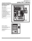
Galaxy PW
TM
100 to 225 kVA