


10 Description of Galaxy PW
TM
Cabinets
Description of Galaxy
PW™ Cabinets
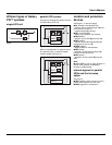
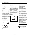
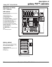
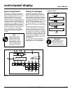
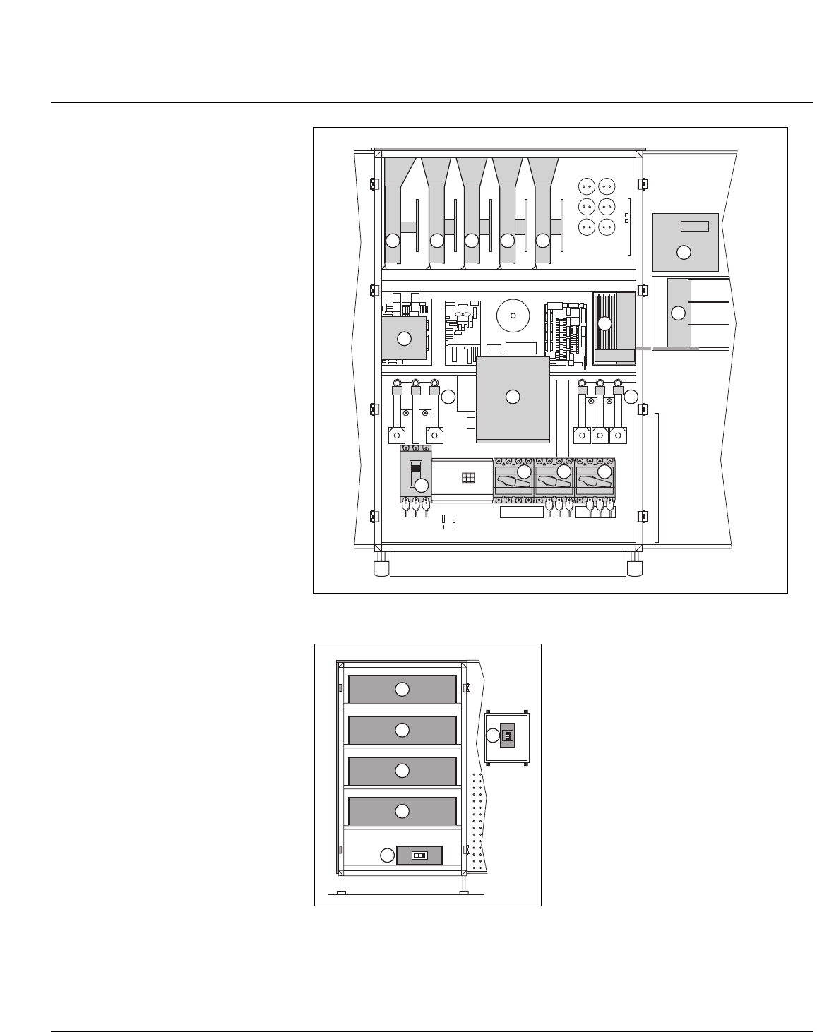
UPS cabinet
See figure 12 for the layout of the various
cabinet components.
Legend for figure 12:
1 - rectifier/charger module,
2 - inverter module,
3 - static-bypass module,
4 - card case for electronic control boards,
5 - rectifier/charger input fuses "FUE",
6 - inverter output fuses "FUS",
7 - normal AC input circuit breaker Q1,
8 - bypass AC input switch Q4S,
9 - maintenance bypass switch Q3BP
(locked in open position on parallel UPSs
for greater capacity),
10 - output switch Q5N,
11 - display board,
12 - Media Contacts 11 remote indications
board,
13 - backfeed protection.
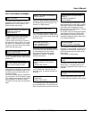
battery cabinet
Figure 13 shows an example of compo-
nent layout in a battery cabinet or a bat-
tery circuit-breaker enclosure.
Legend for figure 13:
1 - battery isolation and protection circuit
breaker QF1,
2 - battery cells.
Fig. 13
Example only and may not represent actual units shipped
Fig. 12
11
12
1 2 2 2 3
3
4
8
9
10
5 6
13
GND
N
7
2
2
2
2
1
1
Galaxy PW
TM
100 to 225 kVA
description of
galaxy PW™ cabinets