


28
maintenance
configuration
single-UPS unit
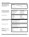
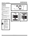
See figure 19. During maintenance, the
UPS must be isolated from the normal and
bypass AC source, the battery and the
load.
■ UPS isolation
Proceed in the following order (see figure
20):
❏ shut down the inverter (press the "invert-
er OFF" button 8 for three seconds),
❏ close bypass switch Q3BP,
❏ open isolating switches Q5N, Q4S, QF1
and Q1.
The UPS is powered down once the
capacitors have discharged (a few min-
utes);
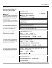
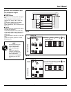
■ start-up
Following servicing, proceed in the follow-
ing order (see figure 21):
❏ close switch Q1, then after approximate-
ly ten seconds, switches QF1, Q5N and
Q4S,
❏ open bypass switch Q3BP,
❏ start the inverter (press the "inverter ON"
button 7 ).
CAUTION
■ work should be car-
ried out in accordance
with applicable safety
regulations;
■ to avoid interrupting
the load, the various
switching operations
must be carried out in the
correct order. Operations
are explained in dia-
grams placed next to the
switches;
■ the system cabinet is
only partially powered
down. The load is still
supplied via the bypass
AC source and switch
Q3BP.
Maintenance
Fig. 21Fig. 20
Fig. 19
Q1
Q5N
QF1
Q3BP
Q4S
AB
C
D
1
2
1
0
1
0
1
0
1
0
1
0
1
0
1
0
1
0
1
0
Q5NQ1 Q4S
3
1
2
1
0
Q3BP
1
0
1
0
5
4
6
QF1
0
I
1
0
1
0
1
0
1
0
OFFOFF
1
0
1
0
1
0
1
0
Q5NQ1 Q4S
3
1
2
Q3BP
1
0
5
4
6
1
0
1
0
1
0
OFF
1
0
QF1
0
I
1
0
1
0
1
0
1
0
maintenance
Galaxy PW
TM
100 to 225 kVA