


15
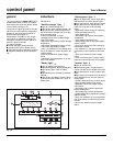
control-panel display
general organization
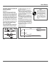
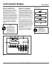
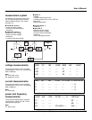
The display is structured around primary
and secondary messages, measuring
tables and setting screens. As a rule, the
message displayed on the screen is
always a primary one. The secondary
messages, if any, are accessed by press-
ing keys 9 ▼ and 10 ▼ (see figure 16).
The presence of secondary messages is
indicated by the arrow
↓↓
at the end of the
primary message. Return to the primary
messages is automatic if the keypad is not
used for 2 minutes, or direct by pressing
key 17 (see figure 14). The display
screen lights up when a key is pressed,
and goes off if no key is pressed for 5
minutes.
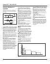
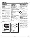
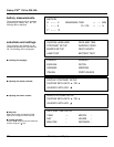
display of messages
In addition to keypad operations, the
graphical display brings up a window giv-
ing the overall device status. The mes-
sage displayed is then said to be primary
(see list in the paragraph below). A prima-
ry message can be used to access the
measuring tables using keys 13 , 14 , 15
and 18 on the keypad (see figure 17 in
the general appendix). The configuration
screens can be accessed by pressing key
12 .
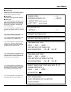
A flashing arrow appears at the end of a
primary message if there is a problem or
an alarm; secondary messages can be
accessed by pressing key 9 on the key-
pad (see the list of secondary messages).
The presence of another message is indi-
cated by the arrows
↓↓
and
↑↑
at the end
of the secondary message. They can be
accessed by pressing keys 9 and 10
on the keypad.
The return to the primary message is
automatic after a 2 minute time delay or
by pressing key 17 on the keypad.
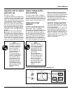
IMPORTANT
Select English U. S. as
the display language to
match the displays as
presented in this manual.
NOTE
Most functions may be
directly accessed. For
example, when voltage
measurements are cur-
rently displayed, it is pos-
sible to directly access
current measurements by
pressing the "A" button.
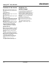
Control-panel Display
Fig. 18
(ALARM MESSAGE N° 2)
(LAST ALARM MESSAGE)
primary message
main screen
(ALARM MESSAGE N° 1)
Display of alarms
Fig. 17
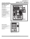
1
2
V A W.Hz
fault
18
17
8
7
643 521
22
2119 20
16
9 10 11 12 13 1514 15
User’s Manual