8 Introduction
inverter shutdown or
overload
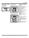
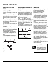
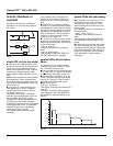
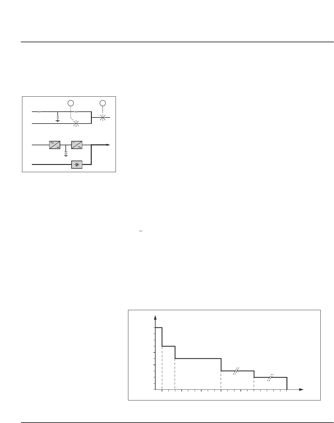
See figure 9 for devices or installations
operating in on-line mode with a bypass
AC source.
Fig. 9
single-UPS unit (on-line mode)
■ in the event of a UPS shutdown (initiat-
ed by the user or by an internal protective
device), the load is automatically trans-
ferred to the bypass AC source. If transfer
conditions are satisfied, transfer takes
place instantly, without interruption to the
load;
Note: transfer conditions are not satisfied
when bypass AC source characteristics
are outside tolerances (voltage: ±10%; fre-
quency as per personalization; phase sync
with inverter ±3°);
■ in the event of a major transient over-
load (greater than 1.65 In), immediate
transfer takes place as above, without
interruption to the load.
The return to the inverter is automatic
when the overload disappears if the num-
ber of possible returns has not been
reached (0 to 255, programmable by per-
sonalization). If this number has been
reached, the load continues to be supplied
by the bypass AC source. This operating
mode allows start-up of load devices
causing high inrush currents.
This system requires satisfied transfer
conditions.
If the conditions are not satisfied, the
inverter will current limit to 165% of its
rated current for 1 second before stop-
ping;
■ in the event of a small but extended
overload (i.e. a continuous level of power
exceeding the full rated load), the inverter
will continue to supply power for a period
depending on the magnitude of the over-
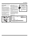
load (10 minutes for a 125% overload, 1
minute for a 150% overload). See the
overload curve in figure 10;
■ in all three of the above cases, inverter
shutdown and supply of the load via the
bypass AC source results in the following
on the control panel:
❏ light 4 goes off,
❏ activation of the buzzer (continuous
beep),
❏ light 3 shines green,
❏ the message "LOAD NOT PROTECT-
ED, ON-LINE MODE" is displayed.
parallel UPSs without redun-
dancy
The shutdown of one inverter results in
overload on the other inverters in opera-
tion. Two cases may then arise:
■ if the overload on each remaining invert-
er is >
than 1.65 ln, the load is immediate-
ly transferred to the bypass AC source;
■ if the overload is less than 1.65 ln, the
remaining inverters support the overload
(see curve in figure 14), and the load is
transferred to the bypass AC source;
■ after this transfer:
❏ the light 4 goes off,
❏ the buzzer is activated and sounds con-
tinuously,
❏ the light 3 goes on and turns green,
❏ the message "LOAD NOT PROTECT-
ED, PARALLEL ON-LINE MODE" is dis-
played.
Fig. 10
parallel UPSs with redundancy
■ the shutdown of one UPS unit is of no
consequence for the load. The others
each take up an equal amount of load
power and the load continues to be sup-
plied normally;
Unit shutdown results in the following on
the control panel:
❏ lights 4 and 5 go off,
❏ activation of the buzzer (continuous
beep),
❏ the message "LOAD NOT PROTECT-
ED, PARALLEL ON-LINE MODE" is dis-
played;
■ in the event of an overload, the system
only loses its redundancy as long as the
overload is less than the total rated power
of the functioning units. If the overload is
greater, the operating mode is that previ-
ously described for systems without
redundancy.
2
1
1
2
AB
C
D
3 5
I
12345678910
(min)
1,5 In
1,35 In
1,25 In
1,15 In
1,10 In
1,05 In
In
t
30 120
Galaxy PW
TM
100 to 225 kVA


