


19
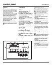
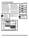
measurement system
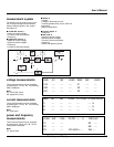
The display may be used to read a num-
ber of input and output measurements
made at different points in the system.
See figure 18 .
■ normal AC source 1
❏ phase-to-phase voltages,
❏ currents of the three phases,
❏ frequency;
■ bypass AC source 2
❏ phase-to-neutral voltage,
❏ phase-to-phase voltages,
❏ frequency,
❏ currents of the three phases;
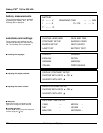
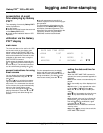
voltage measurements
These measurements may be accessed
by pressing the "V" key 13 . The following
data is displayed.
Note:
M1: normal AC source
M2: bypass AC source
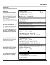
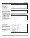
current measurements
These measurements may be accessed
by pressing the "A" key 14 . The following
data is displayed.
Note:
CF: crest factor
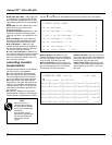
power and frequency
measurements
These measurements may be accessed
by pressing the "W.HZ" key 16 . The fol-
lowing data is displayed.
Note:
PF: power factor
■ battery 3
❏ voltage;
❏ charge or discharge current;
❏ remaining battery time (for the UPS unit
concerned);
❏ battery temperature;
■ inverter output 4
❏ frequency;
■ total load 6
❏ phase-to-neutral voltage,
❏ phase-to-phase voltages,
❏ currents of the three phases,
❏ frequency,
❏ active and apparent power.
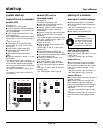
Control-panel Display
1
2
Q1
Q5N
QF1
U - V - I - F
U - I - F
U - I
F
U - V - I - F - P
AB
C
D
Q4S
6431
2
Fig. 19
LOAD KW KVA PL/PN = --- % FREQ.HZ
P1 ---- ---- M1 --.-
P2 ---- ---- M2 --.-
P3 ---- ---- FP.LOAD = -.- INV --.-
RMS M1 M2 LOAD FC-LOAD I-LOAD/I-NOM
I1 ---- ---- ---- -.-- ---- %
I2 ---- ---- ---- -.-- ---- %
I3 ---- ---- ---- -.-- ---- %
RMS M1 M2 LOAD RMS M2 LOAD
U12 ---- ---- ---- V1 ---- ----
U23 ---- ---- ---- V2 ---- ----
U31 ---- ---- ---- V3 ---- ----
User’s Manual