29
parallel UPS redundant and
for increased output
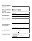
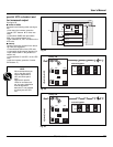
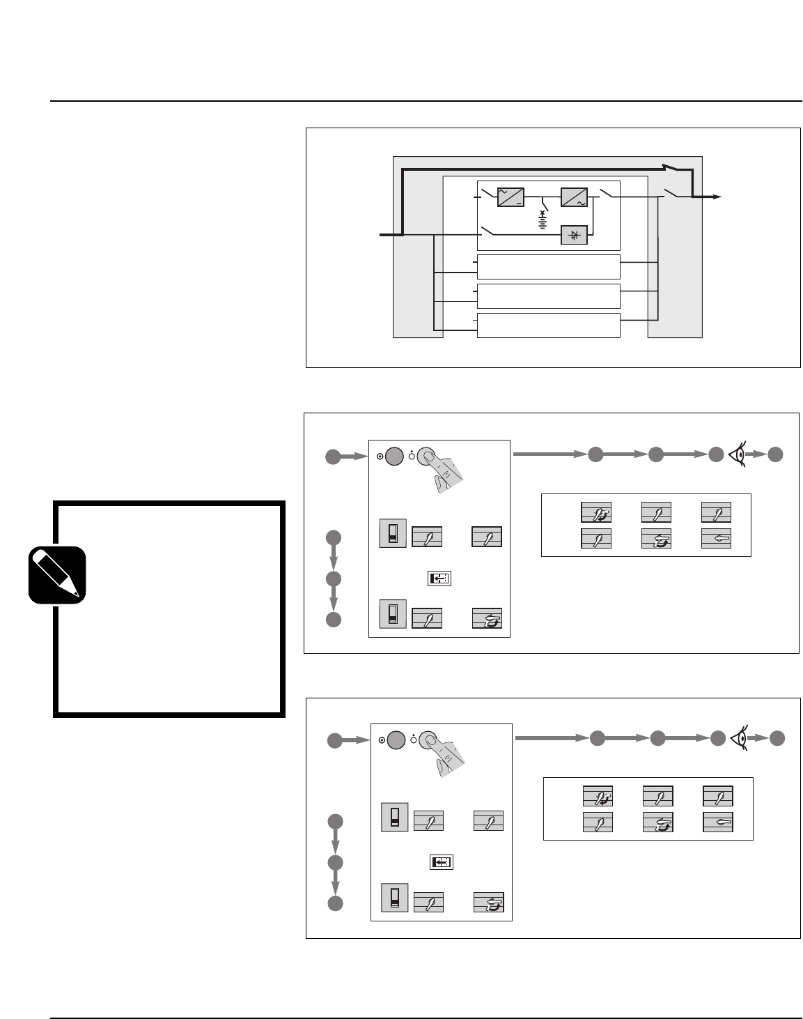
See figure 22.
■ isolate all UPSs
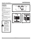
Proceed in the following order (see figure
23):
❏ shut down the inverters (press the
"inverter OFF" buttons 8 for three sec-
onds),
❏ close switch Q3BP and open switch
Q5N in the external bypass unit,
❏ open switches Q1, QF1 and Q5N on the
UPS units.
■ start-up
Following servicing, proceed in the follow-
ing order (see figure 24):
❏ close switches Q5N on the UPS units,
❏ close switch in the external bypass unit,
❏ open switch Q3BP in the parallel-con-
nection unit,
❏ close switches Q1 and QF1 on the UPS
units,
❏ start the inverters (press the "inverter
ON" buttons 7 ).
NOTE
We recommend that you
call on the after-sales
support department to
carry out these opera-
tions.
Note that for parallel
UPSs for increased out-
put, the entire installation
must be bypassed
because it is not possible
to isolate just one UPS
unit.
Maintenance
Fig. 24
Fig. 23
Fig. 22
2 3 4 5
1
0
1
0
1
0
1
0
Q5N
Q3BP
Q5NQ1 Q4S
QF1
0
I
external bypass
7
5
6
1
Galaxy PW
1
0
1
0
1
0
1
0
1
0
1
0
1
0
1
0
1
0
2 3 4 5
1
0
1
0
1
0
1
0
Q5N
Q3BP
Q5NQ1 Q4S
QF1
0
I
external bypass
7
5
6
1
Galaxy PW
1
0
1
0
1
0
1
0
1
0
1
0
1
0
1
0
1
0
2
1
Q3BP
Galaxy 1
Galaxy 2
2
1
Galaxy 3
2
1
Galaxy 4
2
Q5N
1
2
Q1
QF1
Q5N
Q4S
User’s Manual


