


User Guide
42
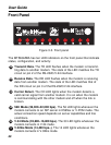
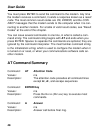
Front Panel
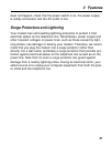
Figure 3-3. Front panel
The MT5634ZBA has ten LED indicators on the front panel that indicate
status, configuration, and activity:
TD
Transmit Data. The TD LED flashes when the modem is transmit-
ting data to another modem. The state of the LED matches the TD
circuit on pin 2 of the RS-232C/V.24 interface.
RD
Receive Data. The RD LED flashes when the modem is receiving
data from another modem. The state of the LED matches that of
the RD circuit on pin 3 of the RS-232C/V.24 interface.
CD
Carrier Detect. The CD LED lights when the modem detects a
valid carrier signal from another modem. It is on when the modem
is communicating with the other modem and off when the link is
broken.
56
56K Mode (56,000–32,000 bps). The 56 LED lights whenever the
modem connects to an ISP server in K56flex or V.PCM mode. The
actual connection speed depends on server capabilities and line
conditions.
33
V.34 Mode (33,600–16,800 bps). The 33 LED lights whenever the
modem connects in V.34 mode.
14
V.32bis Mode (14,400 bps–). The 14 LED lights whenever the
modem connects in V.32bis mode.