


TTD-98055N page 3 of 44
Table of Contents
1.0 WARNING AND LIMITED WARRANTY..................................................................................2
2.0 OVERVIEW.........................................................................................................................................5
Basic Components and Key Features of the C3 Series.....................................................................................5
Optional Components....................................................................................................................................5
3.0 INPUT/OUTPUT TYPES................................................................................................................6
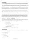
3.1 Input/Output Types and Specifications for the Centurion C3-1...................................................................6
3.1.1 Digital Inputs (DI)..........................................................................................................................6
3.1.2 Analog Inputs (AI) ........................................................................................................................7
3.1.3 Thermocouple Inputs (TC)...........................................................................................................7
3.1.4 Magnetic Pickup (MPU)...............................................................................................................8
3.1.5 Digital Outputs (DO).....................................................................................................................8
3.1.6 Types and Specifications for the Optional Analog Output on the Centurion C3-1 -A....................9
Analog Outputs (AO).............................................................................................................................9
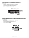
3.2 Input/Output Types and Specifications for the Optional C3-2 Expansion Module to the Centurion C3-1.........9
3.2.1 Analog Inputs (AI)........................................................................................................................9
3.2.2 Thermocouple Inputs (TC)......................................................................................................... 10
3.2.3 Analog Outputs (AO)..................................................................................................................10
4.0 HAZARDOUS AREA OPERATION.........................................................................................10
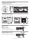
5.0 HARDWARE INSTALLATION AND WIRING.....................................................................11
5.1 Mounting the Centurion Controller.........................................................................................................11
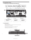
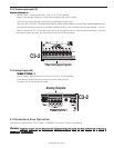
5.2 Mounting the Centurion C3-3 Display.....................................................................................................11
5.3 Power Supply Wiring.............................................................................................................................11
Power........................................................................................................................................................11
Centurion C3-1 I/O Module...................................................................................................................11
Centurion C3-2 Optional Expansion Module...........................................................................................11
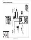
5.4 Wiring the Centurion C3-3 Display.........................................................................................................12
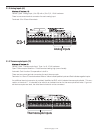
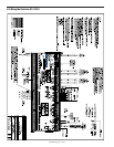
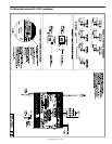
5.5 Wiring the Centurion C3-1/C3-2.........................................................................................................13/14
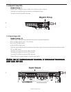
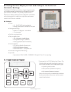
6.0 USING C3-3 DISPLAY TO VIEW AND CONFIGURE
THE CENTURION CONTROLLER SETTINGS.............................................................................15
6.1 Features..............................................................................................................................................15
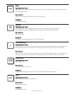
6.1.1 Keypad Description and Navigation..........................................................................15/16/17/18
6.1.2 Display Context........................................................................................................................19
6.1.3 Numeric Entry..........................................................................................................................19
6.2 Operational Screens.............................................................................................................................20
6.2.1 Default Operating Screen......................................................................................................... 20
6.2.2 F W Murphy Logo Screen........................................................................................................ 20
6.2.3 Corporate and Version Information Screen.............................................................................. 20
6.2.4 Shutdown History Screen........................................................................................................ 21
6.2.5 Event History Screen................................................................................................................21
6.2.4 Active Alarms Screen...............................................................................................................21
6.2.5 Gage Display...........................................................................................................................22
6.2.6 Line By Line............................................................................................................................ 22
6.2.7 Custom PID Screen............................................................................................................22/23
6.3 Setup Screens and Menus.....................................................................................................................23
6.3.1 Password Screen.....................................................................................................................23
6.3.2 Digital Input..............................................................................................................................24
6.3.3 Digital Output...........................................................................................................................24
6.3.4 Analog Input........................................................................................................................24/25
6.3.5 Analog Output.....................................................................................................................25/26