


CE-05171N page 36 of 44
kk))
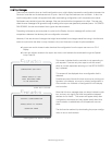
Modbus Requests
ll))
Modbus Responses
mm))
Modbus Exceptions
nn))
Modbus Invalid Response
oo))
Modbus No Response
pp))
Clear Statistics
qq))
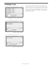
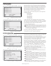
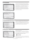
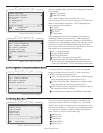
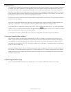
Modbus Register
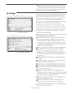
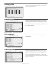
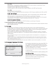
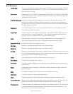
66..33..2255 PPIIDD DDiiaaggnnoossttiiccss
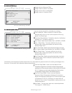
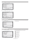
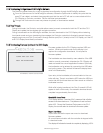
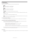
For each of four (4) configured PIDs, user may select to edit:
aa))
Display PID Bar Graph: To monitor the results of modify-
ing the PID components.
bb))
Proportional: To modify the proportional component.
cc))
Integral: To modify the integral component.
dd))
Derivative: To modify the derivative component.
ee))
Auto/Manual: To set to manual mode to allow the corre-
sponding Control Output setting to be adjusted.
ff))
Set Output (Manual):
TM
C
C
C
Communication Status Screen 2
___________________________________
▼
▼
▼
▼
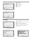
COMMUNICATION STATUS
MODBUS REGISTER
REG: 40001 VAL: 00000
▲▼ ENTER-EDIT
MORE MENUS
___________________________________
___________________________________
TM
C
C
C
Communication Status Screen 3
___________________________________
▼
▼
▼
▼
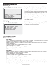
COMMUNICATION STATUS
MODBUS REGISTER
REGISTER: 40001
_
▲▼ ENTER-ACCEPT
ESD-CANCEL
___________________________________
___________________________________
TM
C
C
C
Diagnostic PIDs Screen
___________________________________
▼
▼
▼
▼
PID DIAGNOSTICS
PID 1
PID 1
PID 2
PID 3
PID 4
▲▼ ENTER-SUBMENU
MORE MENUS
___________________________________
___________________________________
TM
C
C
C
Diagnostic PIDs Screen 2
___________________________________
▼
▼
▼
PID 1 OPTIONS
DISPLAY PID BAR GRAPH
NO
PROPORTIONAL
INTEGRAL
DERIVATIVE
▲▼ ENTER-SUBMENU
MORE MENUS
___________________________________
___________________________________
AUTO/MANUAL
Diagnostic PIDs Sreen 3
TM
C
C
C
SETPOINT 75 PSI
75%
75%
80%
LINE PRESSURE 65 PSI
CONTROL OUTPUT
SUCTION PID
ESC-EXIT
___________________________________