


TTD-98055N page 4 of 44
6.3.6 Thermocouple Input................................................................................................................26
6.3.7 General Timer Setup...............................................................................................................27
6.3.8 Maintenance Timer Setup.......................................................................................................28
6.3.9 Set points Setup.....................................................................................................................29
6.3.10 Control Output Setup.......................................................................................................29/30
6.3.11 PID Setup.............................................................................................................................30
6.3.12 Initial RPM Setup.................................................................................................................. 31
6.3.13 Miscellaneous Setup.............................................................................................................31
6.3.14 Lube No Flow Set Up........................................................................................................... 32
6.3.15 Lube No Flow Status............................................................................................................ 32
6.3.16 Super User Menu............................................................................................................ 32/33
6.3.17 Configuration Download (Download Only Screen)................................................................. 33
6.3.18 Display Board Status.............................................................................................................33
6.3.19 Digital Input Status................................................................................................................ 34
6.3.20 Digital Output Status............................................................................................................. 34
6.3.21 Analog Input Status...............................................................................................................34
6.3.22 Analog Output Status.......................................................................................................34/35
6.3.23 Thermocouple Status............................................................................................................35
6.3.24 Communication Status.....................................................................................................35/36
6.3.25 PID Diagnostics.....................................................................................................................36
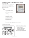
6.4 Additional Navigational Aids................................................................................................................37
6.4.1 Function Key...........................................................................................................................37
6.4.2 Help Key................................................................................................................................. 37
7.0 COMMUNICATIONS...................................................................................................................37
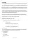
7.1 Communication Ports..........................................................................................................................37
Port 1 (SERIAL)................................................................................................................................37
Port 2 (SERIAL)................................................................................................................................37
Port 2 (USB).....................................................................................................................................38
Port 3 (CAN).....................................................................................................................................38
7.2 Downloading Configurations and Firmware Updates............................................................................. 38
7.2.1 Boot Loader...........................................................................................................................38
7.2.2 Downloading Configurations Via C3-3 Display........................................................................ 38
Special 35 Jump Code................................................................................................................... 38
7.2.3 Downloading Configurations Via MConfigPro Software...........................................................39
7.2.4 Pass Through.........................................................................................................................39
7.2.5 Downloading Firmware Updates to the C3-3 Display..............................................................39
Special 35 Jump Code....................................................................................................................39
Super User Menu............................................................................................................................39
7.2.6 Error Messages......................................................................................................................40
7.3 Modbus Protocol.................................................................................................................................41
7.4 Features of Transferring Data in Modbus.............................................................................................. 41
7.5 Modbus Register Address Listings........................................................................................................41
8.0 GLOSSARY.....................................................................................................................................42
9.0 APPENDICES
.................................................................................................................................43
9.1 Back Panel LED Description.................................................................................................................43
9.2 Controller Accuracies, and Tolerances ...............................................................................................43
9.3 Restrictions on Numeric Values in Gage and PID Monitor Screens..........................................................43
9.4 Set Up Sheet.......................................................................................................................................43
9.0 How to Order................................................................................................................................ 44