


CE-05171N page 37 of 44
6.4 Additional Navigational Aids
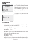
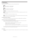
66..44..11 FFuunnccttiioonn KKeeyy
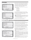
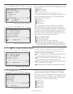
Pressing the Function (Fn) key from any screen will display a
dialog box on the bottom half of the screen. All available func-
tion key commands will be displayed there. The user can then
press a single key for the available commands.
In this case, the user can select from a help screen, the alarms
screen or issue a remote mode command. If the Fn key is not
followed by another key press in five seconds, function mode
will time out and the dialog box will go away restoring the previ-
ous screen.
Note: In all cases the Fn key options will be context sensitive.
Some options will only be available from certain screens or
under certain conditions.
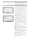
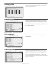
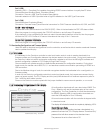
66..44..22 HHeellpp KKeeyy
This is the help screen the user will see by pressing the HOME
key from the Fn dialog box or by pressing the Fn key followed
by the HOME key from a normal screen.
7.0 Communications
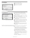
7.1 Communication Ports
Port 1 (SERIAL)
Port 1 is intended as the primary port for the local device, the C3-3 Display, and should be utilized for C3-3 Display
in order for the boot loader mode to properly execute in pass-thru mode.
Interface: Refer to the Sequence of Operations to determine how the communication port has been configured.
Protocol: Modbus (Slave)
Connection: There are three (3) screw terminal connectors for RS485.
These are identified as A, B, and SHD.
There are three (3) screw terminal connectors for RS232.
These are identified as RX, TX, and DTR.
SHD is common for both ports.
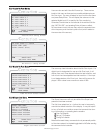
Port 2 (SERIAL)
Interface: Refer to the Sequence of Operations to determine how the communication port has been configured.
INSERT DIAGRAM? RICK NOTES ON PREVIOUS MARKUP
Protocol: Modbus (Slave), Proprietary (Binary)
Connection: There are three (3) screw terminal connectors for RS485.
These are identified as A, B, and SHD.
There are three (3) screw terminal connectors for RS232.
These are identified as RX, TX, and DTR.
SHD is common for both ports.
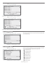
Modbus Slave Address Configuration: The operator may assign a unique Modbus address to each controller
(slave) unit that may be in the system. This allows the master controller to differentiate between the modules. For
example, to name the controller address 21, place the shunts on LK1, LK4, and LK16 (1 + 4 +16 = 21). Typically,
this configuration is set to (1) by the factory.
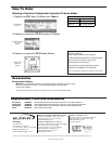
Fn Key Dialog Box Screen
TM
C
C
C
Fn-EXIT HOME-HELP
___________________________________________________
ACK-ALARMS SCREEN
REMOTE MODE COMMANDS:
RESET AND RUN/STOP
FW MURPHY - MVIEW
WWW.FWMURPHY.COM
SALES@FWMURPHY.COM
(918) 317-4100
TM
C
C
C
▼
Help Screen
▼
PRESS ANY KEY TO EXIT
-MOVES SCREEN TO SCREEN
▲▼ -MOVES LINE TO LINE
HOME-TOP LINE OF SCREEN
HOME AGAIN-MAIN SCREEN
___________________________________