


Chapter 4 Controller Synthesis
© National Instruments Corporation 4-3 MATRIXx Xmath Robust Control Module
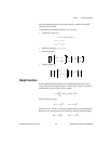
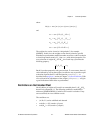
Equivalently, as a transfer matrix:
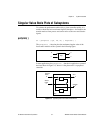
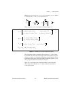
To enter the extended system, you must know the sizes of e and w shown
in Figure 4-1. The extended plant P can be constructed using the Xmath
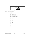
interconnection functions, as shown in Example 4-1.
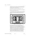
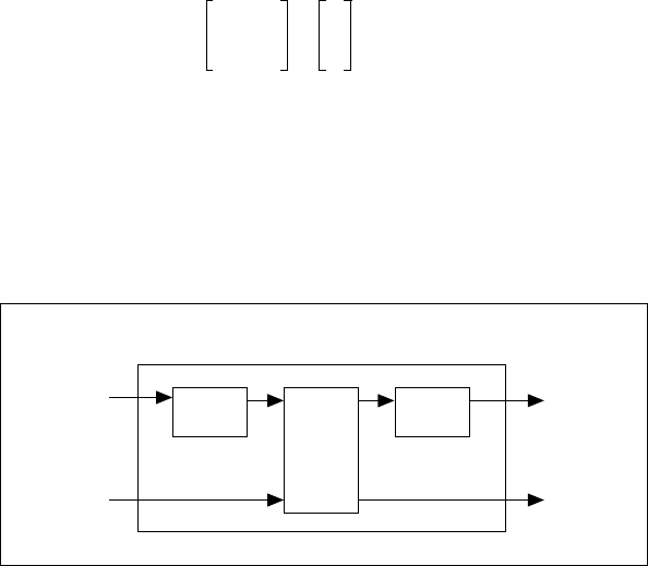
Building the Plant Model
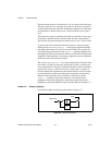
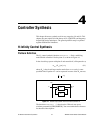
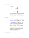
The general form of the plant P is shown in Figure 4-2.
Figure 4-2. Construction of Plant P
The plant consists of three transfer matrices: W
in
and W
out
, referred to as
weights, and G which can be interpreted as the system dynamics. Both P
and G distinguish inputs and outputs into two groups of variables.
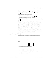
The input/output variables are organized as follows:
• actuator/sensor variables
u—vector of actuator (control) signals
y—vector of sensor (measured) and other accessible signals
• exogenous inputs
v—vector of commands and disturbance
w—vector of “normalized” commands and disturbances
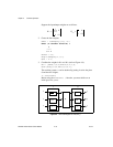
• performance outputs
z—vector of critical performance signals (regulated variables)
e—vector of “normalized” critical performance signals
Ps()
D
11
D
12
D
21
D
22
C
1
C
2
sI A–()
1–
B
1
B
2
[]+=
w
vz
e
u
y
Plant P
G
W
in
W
out