


Chapter 6 Using Your Serial Hardware
Serial Hardware and Software for Windows 6-4 ni.com
The scratch register is located at offset 7 from the base address of the port.
For example, if COM2 were located at base address 0x3F8, and you want
to set the board to two-wire mode with DTR
control, you would write a
0x02 to address 0x3FF. The board would immediately switch to the
two-wire mode with DTR
control.
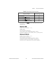
Windows NT
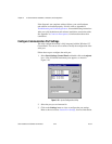
To set the transceiver control mode, use the serial configuration utility.
For instructions on how to use the utility, refer to chapter with installation
instructions for your hardware platform. The mode you select in the
configuration utility is automatically configured when you open a port on
a serial interface.
Setting the Transceiver Mode with DeviceIoControl
The NI-Serial software extends the
DeviceIoControl
Windows function
for programming the transceiver control mode. To program the transceiver
control mode using
DeviceIoControl
, complete the following steps:
1. Add the following lines to your source code:
#include <winioctl.h>
#define IOCTL_SERIAL_SET_TRANSCEIVER_MODE
CTL_CODE(FILE_DEVICE_SERIAL_PORT,37,
METHOD_BUFFERED,FILE_ANY_ACCESS)
2. Use the Win32 function
DeviceIoControl
, as follows:
a. Use the defined control code value listed in step 1 to set the
transceiver mode.
b. Use the input buffer values (unsigned long) listed in Table 6-3 for
programming different transceiver modes.
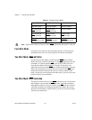
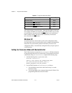
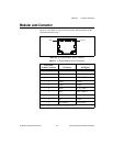
Table 6-2. Transceiver Mode Control Bytes
Transceiver Mode Control Byte
Four-wire mode 0x00
Two-wire mode: DTR with echo 0x01
Two-wire mode: DTR controlled 0x02
Two-wire mode: TXRDY auto control 0x03