


© National Instruments Corporation I-1 Serial Hardware and Software for Windows
Index
Numerics
100-pin connector, A-8
pin descriptions (table), A-9
pin locations (figure), A-8
10-position modular jack, A-3
pin descriptions (table), A-3
pin locations (figure), A-3
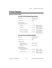
16-port boards specifications
PCI, E-3
PXI, E-6
68-pin connector, A-6
pin descriptions (table), A-7
pin locations (figure), A-6
A
advanced port settings
AT, Windows Me/9x,5-17
dialog box (figure)
AT, Windows Me/9x,5-17
PCI, Windows Me/9x,2-17
PCMCIA, Windows Me/9x,4-15
PXI, Windows Me/9x,3-16
PCI, Windows Me/9x,2-17
PCMCIA, Windows Me/9x,4-15
PXI, Windows Me/9x,3-16
transceiver mode
AT, Windows Me/9x,5-17
PCI, Windows Me/9x,2-17
PCMCIA, Windows Me/9x,4-15
PXI, Windows Me/9x,3-16
advanced settings
AT, Windows 2000, 5-8
dialog box (figure)
AT, Windows 2000, 5-8
PCI, Windows 2000, 2-8
PCMCIA, Windows 2000, 4-7
PXI, Windows 2000, 3-8
PCI, Windows 2000, 2-8
PCMCIA, Windows 2000, 4-7
PXI, Windows 2000, 3-7
transceiver mode
AT, Windows 2000, 5-8
PCI, Windows 2000, 2-8
PCMCIA, Windows 2000, 4-7
PXI, Windows 2000, 3-8
using FIFO buffers, 2-9, 2-17, 3-8, 3-16,
4-8, 4-15, 5-9, 5-18
advanced transceiver control, 6-1
four-wire mode, 6-2
setting transceiver control mode, 6-3
transceiver mode control bytes (table), 6-4
transceiver mode control modes (table), 6-2
two-wire mode: DTR
controlled, 6-2
two-wire mode: DTR
with Echo, 6-2
two-wire mode: TXRDY
auto control, 6-3
AT serial board installation (figure), 5-3,
5-11, 5-20
B
bias resistors, B-5
using in transmission line (figure), B-6
C
cable connection, A-1
changing communication port settings
Windows 2000, 2-5, 3-5, 4-5, 5-5
Windows NT, 2-21, 3-20, 4-19, 5-22
changing resources assigned to serial
interface, D-16
COM port number, 2-22, 3-21, 4-20, 5-23