


Appendix B Serial Port Information
© National Instruments Corporation B-7 Serial Hardware and Software for Windows
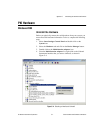
DTE vs. DCE
In the RS-232 specification, DTE (Data Terminal Equipment) and DCE
(Data Communications Equipment)
1
refer to the types of equipment on
either end of a serial connection. In general, DTE and DCE refer to
computer equipment and modems, respectively. Because the RS-232
specification mainly involves connecting a DTE directly to a DCE and vice
versa, the pinouts are defined so that cabling is simple. That is, a cable
connected a computer to a modem by wiring pin 1 to pin 1, pin 2 to pin 2,
and so on. This method is known as straight-through cabling.
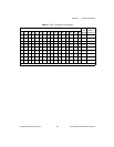
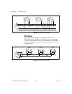
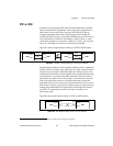
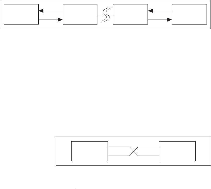
Figure B-5 shows straight-through cabling in a DTE-to-DCE interface.
Figure B-5. Straight-Through Cabling in a DTE-to-DCE Interface
Straight-through cabling is still the standard method to connect a modem to
your PC. However, because many applications use serial communication to
connect two or more DTEs without modems, the cabling becomes more
complicated. If two DTEsare wired togetherusing astraight-through cable,
one transmitter is connected to the other transmitter, and one receiver is
connected to the other receiver. In this setup, no transmissions can occur.
Thus, these applications must use a cabling scheme that connects the
transmitter on one device to the receiver on the other device and vice versa.
This method is known as null-modem cabling, because it replaces the two
modems that traditional RS-232 applications would require between the
two DTEs. To communicate from one serial port to another, use a
null-modem cable.
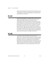
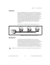
Figure B-6 shows null-modem cabling in a DTE-to-DTE interface.
Figure B-6. Null-Modem Cabling in a DTE-to-DTE Interface
1
In Revision D of the RS-232 specification, a DCE is a Data Circuit-Terminating Equipment.
Rx D
Tx D
Pin 3
Pin 2
DTE
Pin 3
Pin 2
DCE
Pin 3
Pin 2
DCE
Pin 3
Pin 2
DTE
Rx D
Tx D
Rx D
Tx D
Rx D
Tx D
Pin 2
Pin 3Pin 3
Pin 2
DTE DTE