


Chapter 2 Connecting Signals
© National Instruments Corporation 2-3 SCXI-1503 User Manual
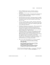
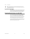
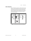
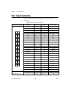
4-Wire Configuration
The 4-wire configuration, also referred to as a Kelvin connection, is shown
in Figure 2-1. The 4-wire configuration uses one pair of wires to deliver the
excitation current to the resistive sensor and uses a separate pair of wires to
sense the voltage across the resistive sensor. Because of the high input
impedance of the differential amplifier, negligible current flows through
the sense wires. This results in a very small lead-resistance voltage drop
error. The main disadvantage of the 4-wire connection is the greater
number of field wires required.
Figure 2-1. 4-Wire Resistive Sensor Connected in a 4-Wire Configuration
External Sensor SCXI-1306
+
–
SCXI-1503
Channel X
IEX+
AI+
AI–
IEX–
I = 100 µA
ON
CH X
R
L3
R
L2
R
L1
R
L4
R
T