


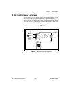
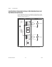

Chapter 2 Connecting Signals
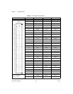
© National Instruments Corporation 2-9 SCXI-1503 User Manual
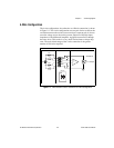
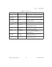
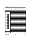
Table 2-2. Signal Descriptions
Pin Signal Name Description
A1 +5 V +5 VDC Source—Used to power circuitry on the
terminal block. 0.1 mA of source not protected.
A13 – A16,
A29 – A32
GND Ground—Tied to the SCXI module ground.
A1, A19, A20,
A25 – A28
RSVD Reserved—This pin is reserved. Do not connect
any signal to this pin.
A2 C GND Chassis Ground—Connects to the SCXI chassis.
B24 – B17,
B8 – B1
IEX<0..7> –,
IEX<8..15> –
Negative Excitation—Connects to the channel
ground reference. This is the return path for the
corresponding IEX+ channel.
C24 – C17,
C8 – C1
IEX<0..7> +,
IEX<8..15> +
Positive Excitation—Connects to the positive
current output of the channel.
A3, A4 CJ SENSOR Cold-Junction Temperature Sensor
Input—Connects to the temperature sensor of
the terminal block.
B30 – B 25,
B16 – B9
AI <0..7> –,
AI <8..15> –
Negative Input Channels—Negative side of
differential input channels.
C32 – C25,
C16 – C9
AI <0..7> +,
AI <8..15> +
Positive Input Channels—Positive side of
differential input channels.