


Chapter 4 Theory of Operation
© National Instruments Corporation 4-3 SCXI-1503 User Manual
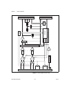
The major components of the SCXI-1503 modules are as follows:
• Rear signal connector
• SCXIbus connector
• SCXIbus interface
• Digital control circuitry
• Analog circuitry
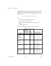
The SCXI-1503 modules consist of 16 multiplexed input channels, each
with a software-programmable gain of 1 or 100. Each input channel has its
own lowpass filter. Each channel has a fixed 100 μA current excitation. The
SCXI-1503 modules also have a digital section for automatic control of
channel scanning, temperature sensor selection, gain selection, and
auto-zero mode.
Rear Signal Connector, SCXIbus Connector, and
SCXIbus Interface
The SCXIbus controls the SCXI-1503 module. The SCXIbus interface
connects the rear signal connector to the SCXIbus, allowing a DAQ device
to control the SCXI-1503 module and the rest of the chassis.
Digital Control Circuitry
The digital control circuitry consists of the Address Handler and registers
that are necessary for identifying the module, reading/setting calibration
information, setting the gain, and selecting the appropriate channel.
Analog Circuitry
The analog circuitry per channel consists of a fixed lowpass filter and an
amplifier with a software selectable gain of 1 or 100. The CJ SENSOR
channel has a lowpass filter buffered by a unity gain amplifier. The
channels and CJ SENSOR are multiplexed to a single output buffer.
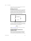
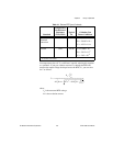
Analog Input Channels
Each of the 16 differential analog input channels feeds to a separate
instrumentation amplifier with a programmable gain of 1 or 100. Each
channel has a fixed 100 μA current excitation. Then the signal passes
through a fixed 2-pole, 5 Hz lowpass filter.