


Chapter 4 Theory of Operation
SCXI-1503 User Manual 4-6 ni.com
changes in resistance, you must use special configurations that minimize
measured errors caused by lead-wire resistance.
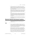
RTD Measurement Errors
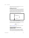
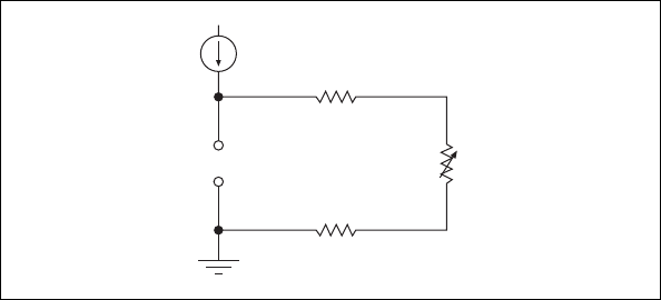
Because the RTD is a resistive device, you must pass a current through the
device and monitor the resulting voltage. However, any resistance in the
lead wires that connect the measurement system to the RTD adds error to
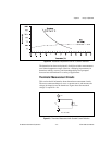
the readings. For example, consider a 2-wire RTD element connected to a
measurement system that also supplies a constant current, I
EX
, to excite the
RTD. As shown in Figure 4-2, the voltage drop across the lead resistances
(labeled R
L
) adds an error voltage to the measured voltage.
Figure 4-2. 2-Wire RTD Measurement
For example, a lead resistance of 0.3 Ω in each wire adds a 0.6 Ω error to
the resistance measurement. For a platinum RTD at 0 °C with α = 0.00385,
the lead resistance equates to an error of approximately
Chapter 2, Connecting Signals, describes different ways of connecting
resistive devices to the SCXI system.
The Relationship Between Resistance and
Temperature in RTDs
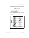
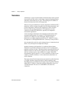
Compared to other temperature-measurement devices, the output of an
RTD is relatively linear with respect to temperature. The temperature
coefficient, called alpha (α), differs between RTD curves. Although
various manufacturers specify alpha differently, alpha is most commonly
R
T
R
L
R
L
I
EX
+
–
V
0
0.6 Ω
0.385 Ω/°C
----------------------------- 1.6 °C=