


Chapter 2 Connecting Signals
© National Instruments Corporation 2-7 SCXI-1503 User Manual
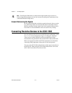
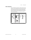
In this configuration, the lead-resistance voltage drop across R
L3
is
converted into a common-mode voltage that is rejected by the differential
amplifier. Also, the polarity of the lead-resistance voltage drops across R
L1
and R
L2
are series opposing, relative to the inputs of the differential
amplifier, eliminating their effect on the voltage measured across R
T
.
Note R
L1
and R
L2
are assumed to be equal.
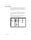
The effectiveness of this method depends on the matching of the current
sources. Each current source on the SCXI-1503 has an accuracy of ±0.05%.
This accuracy results in a worst-case matching of ±0.1%. Refer to the
Chapter 4, Theory of Operation, for accuracy considerations of RTDs and
thermistors.
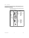
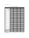
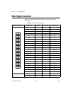
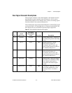
Front Connector
The pin assignments for the SCXI-1503 front signal connector are shown
in Table 2-1.
Note Do not make any connections to RSVD pins.