


Chapter 2 Connecting Signals
SCXI-1503 User Manual 2-12 ni.com
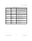
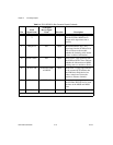
26 SER DAT OU
T
P0.4 Output Serial data out—this signal taps
into the SCXIbus MISO line to
accept serial output data from a
module.
27 DAQ D*/A P0.1 Input Board data/address line—this
signal taps into the SCXIbus D*/A
line to indicate to the module
whether the incoming serial stream
is data or address information.
29 SLOT 0 SEL* P0.2 Input Slot 0 select—this signal taps into
the SCXIbus INTR* line to indicate
whether the information on MOSI
is being sent to a module or Slot 0.
36 SCAN CLK AI HOLD COMP,
AI HOLD
Input Scan clock—a rising edge indicates
to the scanned SCXI module that
the E/M Series DAQ device has
taken a sample and causes the
module to advance channels.
37 SER CLK EXTSTROBE* Input Serial clock—this signal taps into
the SCXIbus SPICLK line to clock
the data on the MOSI and MISO
lines.
43, 46 RSVD RSVD Input Reserved.
Note: All other pins are not connected.
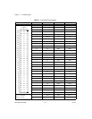
Table 2-4. SCXI-1503 50-Pin Rear Connector Signals (Continued)
Pin
SCXI
Signal Name
NI-DAQmx
Device Signal
Name
Direction Description