


Chapter 2 Connecting Signals
SCXI-1503 User Manual 2-4 ni.com
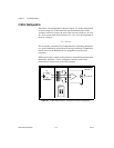
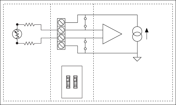
2-Wire Configuration
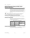
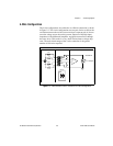
The basic 2-wire configuration is shown in Figure 2-2. In this configuration
an error voltage (V
E
) is introduced into the measurement equal to the
excitation current (I
EX
) times the sum of the two lead resistances, R
L1
and
R
L2
. If we assume equal lead resistances, R
L1
= R
L2
= R
L
, the magnitude of
the error voltage is:
This is the most commonly used configuration for connecting thermistors
to a signal conditioning system because the large sensitivity of thermistors
usually results in the introduction of a negligible error by the lead
resistances.
RTDs typically have a much smaller sensitivity and nominal resistance than
thermistors, therefore a 2-wire configuration usually results in the
introduction of larger errors by the lead resistance.
Figure 2-2. 2-Wire Resistive Sensor Connected in a 2-Wire Configuration
V
E
2R
L
I
EX
=
ON
CH X
+
–
SCXI-1306External Sensor SCXI-1503
Channel X
IEX+
AI+
AI–
IEX–
I = 100 µA
R
L1
R
L2
R
T