4-64
Upgrading Your System
A
B
C
E
D
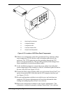
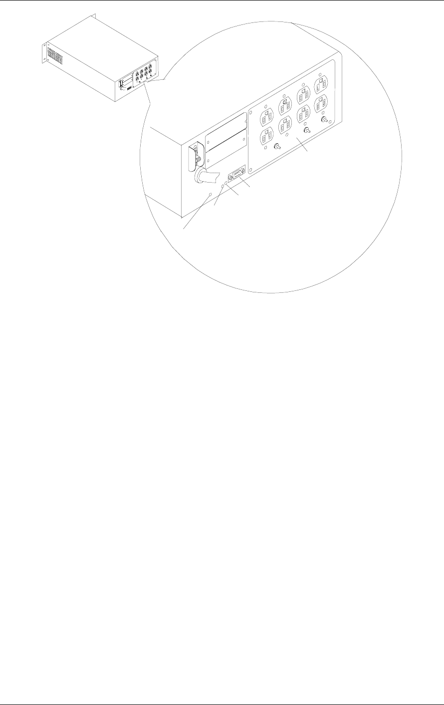
A. Site Wiring Fault Indicator
B. Configuration Button
C. Configuration LED
D. Computer Interface Port
E. Output Power Receptacles
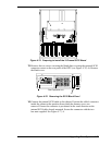
Figure 4-70 Location of UPS Rear Panel Components
10.
If there is no wiring fault, connect the ground lead of any transient voltage
surge-suppression (TVSS) devices such as telephone and network line
protectors. The TVSS connector provides grounding through the UPS’
power cord ground conductor. This provides protection from damage from
surges transmitted via network and phone cables.
11.
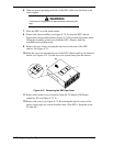
As the installation progresses, connect the power cables from individual
system components to the receptacles of the AC distribution panel located in
the rear of the UPS (see Figure 4-70, E).
12.
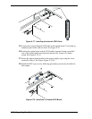
Connect the black smart signaling cable received with the PowerChute
®
plus
option, between the BSU serial port and the UPS computer interface port
(see Figure 4-70, D).
13.
On your configuration worksheet, note which server and serial port are
connected. The System Administrator will need this information when
loading and configuring PowerChute
®
plus software.
14.
Deliver the configuration worksheet to the System Administrator. This
information is required to properly configure PowerChute
®
plus software.


